Basic function principles
The Analog Input Terminal KL306x processes signals in the range between 0 V and +10 V with a resolution of 12 bits (4095 steps). The inputs of the KL306x are single-ended inputs with a common ground potential.
The LEDs indicate the operating state of the associated terminal channels.
- green Run LED:
- On: Normal operation
- Off: Watchdog-timer overflow has occurred. If no process data are transmitted by the Bus Coupler for 100 ms, the green LEDs go out.
Process data output format
In the delivery state the process data are shown in two's complement form (integer -1 corresponds to 0xFFFF). Other presentation types can be selected via the feature register (R32) (e.g. signed amount representation, Siemens output format).
Measured value | Output | |
|---|---|---|
KL306x | dec | hex |
0 V | 0 | 0x0000 |
5 V | 16383 | 0x3FFF |
10 V | 32767 | 0x7FFF |
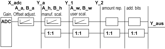
Calculation of process data
The terminal continuously takes measured values and stores the raw values of its A/D converter in register R0 (RAM ). The calculation of the correction with the calibration values takes place after each sampling of the analog signal. This is followed by manufacturer and user scaling:
The process data that are transferred to the Bus Coupler are calculated using the following equations:
Y_a = (B_a + X_adc) * A_a | (1.0) | Neither user nor manufacturer scaling is active. |
Y_1 = B_h + A_h * Y_a | (1.1) | Manufacturer scaling active: (Default setting) |
Y_2 = B_w + A_w * Y_a | (1.2) | User scaling active |
Y_1 = B_h + A_h * Y_a | (1.3) | Manufacturer and user scaling active |
Key
Name | Name | Register |
|---|---|---|
X_adc | Output value of the A/D converter | - |
Y_aus | Process data for controller | - |
B_a | Vendor calibration: Offset | |
A_a | Vendor calibration: Gain | |
B_h | Manufacturer scaling: Offset | |
A_h | Manufacturer scaling: Gain | |
B_w | User scaling: Offset | |
A_w | User scaling: Gain |
The equations of the straight line are enabled via register R32.