KL2751, KL2761 - Contact assignment
| |
Risk of injury through electric shock and damage to the device! Bring the Bus Terminals system into a safe, de-energized state before starting mounting, disassembly or wiring of the Bus Terminals! |

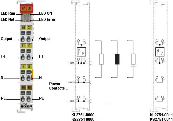
Terminal point | No. | KL2751-0000, | KL2751-0011, |
|---|---|---|---|
Output | 1 | Load (internally connected with terminal point 5) | Load (internally connected with terminal point 5) |
L1 | 2 | Phase (internally connected with terminal point 6 and power contact for L1) | Phase (internally connected with terminal point 6) |
N | 3 | Neutral conductor (internally connected with terminal point 7 and power contact for N) | Neutral conductor (internally connected with terminal point 7) |
PE | 4 | Protective conductor (internally connected with terminal point 8 and power contact for PE) | Protective conductor (internally connected with terminal point 8) |
Output | 5 | Load (internally connected with terminal point 1) | Load (internally connected with terminal point 1) |
L1 | 6 | Phase (internally connected with terminal point 2 and power contact for L1) | Phase (internally connected with terminal point 2) |
N | 7 | Neutral conductor (internally connected with terminal point 3 and power contact for N) | Neutral conductor (internally connected with terminal point 3) |
PE | 8 | Protective conductor (internally connected with terminal point 4 and power contact for PE) | Protective conductor (internally connected with terminal point 4) |
Power feed terminal
It is imperative that you use a power feed terminal (e.g.: KL9150, KL9160, KL9250, KL9260) designed for 230 VAC to supply mains voltage (230 VAC) into the power contacts!
Note | |
Risk of damage to the device! Bus Couplers, Bus Terminal controllers and power supply terminals for 24 V are not suitable for the supply of mains voltage into the power contacts! They are designed only for voltages up to 24 V and would be destroyed if 230 VAC is applied at their power contacts! |
Several dimmer terminals can be operated on one power feed terminal.
 | Separation terminal If 24 V and 230 VAC are to be used on the power contacts in a Bus Terminal block, the KL9080 separation terminal can be used in order to clearly separate the potential blocks visually from each other. |
Short-circuit limitation
The dimmer terminals are equipped with short-circuit current limitation. The current is limited to approx. 10 A to 15 A. Normally triggering of the fuse is therefore prevented.
The short circuit current flows for less than 0.5 ms and is switched on automatically. After a short circuit was detected the KL2751 tries to switch the system on again and tests the line with a low voltage. If the short circuit has been eliminated, the dimmer terminal returns to the previous dimmer value.
A short circuit on the line should always be avoided and never deliberately caused! The components in the dimmer terminal are stressed by short circuits. A large number of short circuits will shorten the service life of the dimmer terminal!
Fuses
The dimmer terminal may be protected with fuses up to 10 A.
The dimmer terminal protects itself against destruction due to short circuit and overload. This built-in protection acts on the connection line between dimmer terminal and load in the event of a short circuit.
Note | |
Risk of damage to the device! However, overload protection must still be provided. The fine-wire fuse often used in devices with transformers must not be bridged or changed in its value. This could lead to overheating of the transformer. |