Notes regarding analog equipment - shielding and earth
Meticulous application of the term “earth” is required, particularly when it comes to reliable use of analog (measuring) signals. The conductive coupling of different potentials, such as earth potential and a housing potential or the earth points of analog devices, can have different aims:
- Earthing as protective measure against the occurrence of dangerous touch voltages (PE)
- Earthing for definition of a common signal potential, in order to ensure the function of analog measurements, for example
- Earthing for discharging of interference or internally generated emissions (FE); keywords: interference immunity and interference emission
In each case the user should be clear which of the above aims is to be achieved through the respective measures. The respective reference earth can have different potential!
The observations, measures and effects described below primarily refer to 3. “FE/functional earth”, taking into account the requirements of 2. “Common reference potential”. Information and specifications relating to 1. “PE” can be found in the relevant guidelines, such as VDE0100, and is not part of this section on analog equipment. The focus and application area of the following notes is for the scope of analog signal transmission.
 | The terms “protective earth” and “functional earth” This section primarily deals with functional earth (FE, |
 ) as a functionally relevant regular part of an installation, in contrast to protective earth (PE, symbol:
  ), which is intended to protect persons from excessive touch voltages.
 | This document This document provides general recommendations based on practical experience, without taking into account specific features of particular installations. These recommendations should be regarded as a collection of technical solution options. System manufacturers should check to what extent the measures described here are applicable to their system, and which of the suggested measures should be implemented. To this end, different measuring and testing techniques should be used. Any problems should be examined thoroughly, in order to ascertain the trigger and the fault location. |
| Lightning protection Lightning protection aspects are not considered. |
| Potentially explosive areas Special regulations and procedures may apply for potentially explosive atmospheres and supply lines for such areas, which are not covered by this documentation. |
| Reference to individual documents Special instructions and documentation relating to the devices used must be followed. |
Recommended procedure in the event of a conspicuousness
- Use this document, other publicly available documents/standards and manufacturer documentation to familiarise yourself with the background and practical characteristics of EMC interference.
Reflect on the mechanism of action between source of interference → transfer path → interference sink. - Use the specified diagnostic methods to isolate the interference sink, i.e. the location/device that does not work properly
- Reflect on how the fault could have occurred, taking into account the background information from section 1.
- Use the information and solution proposals provided to weigh up system-specific options or normative specifications/restrictions. We recommend to only change one component at a time, in order to verify the effectiveness of the respective measure.
- At the same time, use the specified diagnostic methods to ascertain whether the source of interference or the transfer path has been found.
Functional chain: source of interference – coupling – interference sink
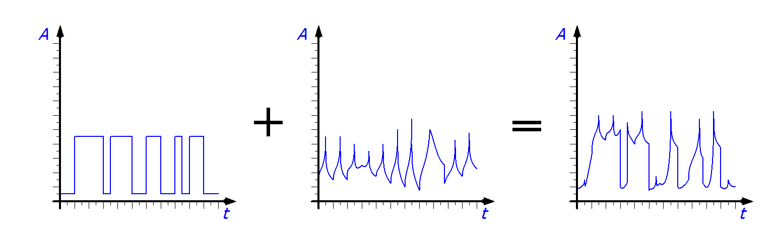
The undesirable effect of a source of interference on an interference sink via the coupling can be reduced or completely suppressed through the measures described below. A fault results in modification of a wanted signal. In the worst case, the recipient of the wanted signal is no longer able to interpret the information content, or its operation is disturbed due to the modified amplitude/frequency or even electrical damaged.
The fault can be transferred by wire or by radiation.
A device can simultaneously act as source of interference and as interference sink (depending on the effective direction).
A cable/device acts as source of interference 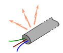 through strong/weak interference effect (emissions, interference emission) due to (e.g.)
- strong/weak interference effect through emissions, i.e. interference emissions
- insufficient suppression through shielding, chokes, filters
- insufficient avoidance through discharge facilities, spark gaps, incorrectly dimensioned termination resistors
A cable/device acts as interference sink 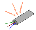 through strong/weak susceptibility to interference, i.e. inadequate immunity to interference due to (e.g.)
- missing or inadequately implemented protection components: shielding, compensating elements, discharge facilities, spark gaps
In general, the following mechanisms are available for coupling a fault with the wanted signal:
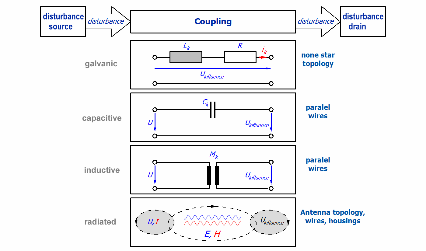
Shielding measures or interference generation prevention may be applied as remedial action.
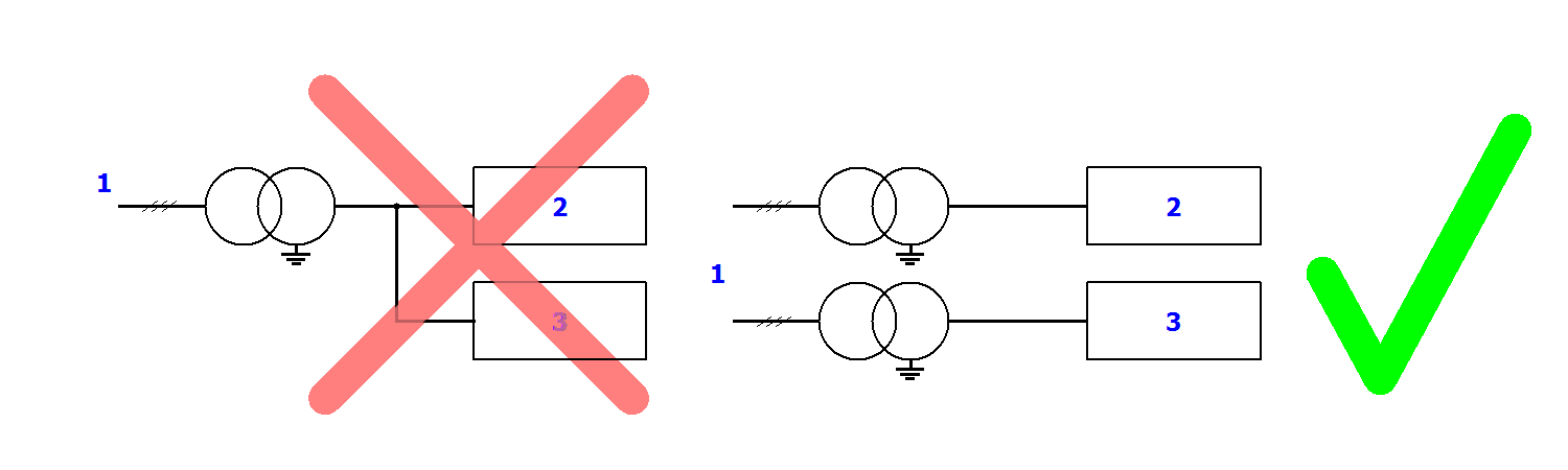
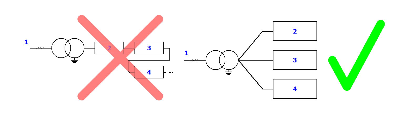
Galvanic coupling – measures against transfer:
- Separation of different potentials, avoidance of equalising currents
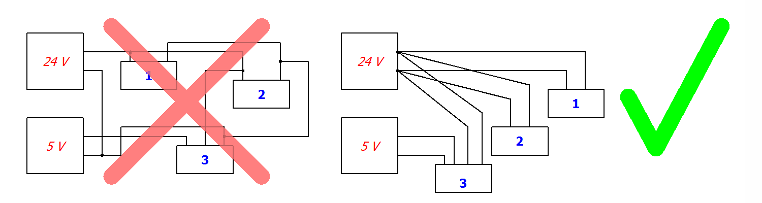
- Star wiring, no ladder network
Capacitive coupling – measures against transfer:
- Spatial separation
- Full, close-meshed shielding of the signal cable without interruption or holes.
Holes in the sense of this documentation are uncovered areas of the order of centimetres.
Significant signal components can be emitted or unintentionally received from a hole with a size of 10 % of the wavelengths. - Single-sided, low-impedance connection of the shielding to system earth
Inductive coupling – measures against transfer:
- spatial separation
- Shielding, see capacitive coupling
- Two-sided, low-impedance connection of the shielding to system earth
- Equidirectional, tight twisting (high twisting rate) of the analog signal cables with each other
Wireless coupling - measures:
- Short cable lengths
- Shielding, see capacitive coupling
Common signal potential, basic measures and notices
In some applications the reference potentials of different devices have to be linked, e.g. in order to be able to perform a measurement.
- Usually, no equalising currents should flow via such connections – for remedial measures see the following section.
- Buffer amplifiers may have to be used in some cases
- Potential-free connections on the device side may be suitable in some cases – note the permitted potential difference!
FE/shielding, basic measures and information
A list of exemplary measures, taking into account the information provided above, which may be considered in order to reduce interference, is provided below.
- Temporal effectiveness: the effectiveness of implemented measures may reduce over time and should therefore be checked regularly, particularly in the event of anomalies. Negative influencing factors include wire break, oxidation at contact points, mechanical damage, change in earthing characteristics, change in environment (new interference sources?), etc.
- Selected reference potential
- The reference potential used for discharge/earthing may itself be subject to interference, so that a connection to it may introduce more interference in the system than it discharges. In this case, a different, low-interference reference potential should be used.
- To ensure good discharge, it may be helpful to install a separate FE earthing point in the building and use it for sensitive signals/shielding.
Caution in the event of lightning strike: a lightning strike in the vicinity can result in large potential differences between buildings and earth, which can affect locally separated earthing equipment. Spark gaps may be able to prevent equipment damage. VDE guidelines must be followed! - Wiring
- The cable connections should be as short as possible
- The denser the cables can be laid over a metallic, grounded area/potential equalization, the less interference can be introduced, and the more interference is discharged capacitively via earth.
- Installation instructions for analog interference-sensitive signal lines next to highly interfering load lines:
- - avoid parallel installation, if unavoidable then separate with a large distance (> 20 cm) from each other, shield from each other with metal separators
- - unshielded cables should be twisted, if possible
- Use wire end sleeves or cable lugs to connect flexible cables/strands. Tinning is no longer permitted.
- Unused wires/cables should be earthed on one side as a minimum.
- All cables in a cable channel must comply with the insulation class of the cable with the highest voltage
- Metal cable channels are preferable for shielding reasons
- Shielding
- Shields must not assume the function of an N or PE conductor.
Functional earth intended for improving EMC (electromagnetic compatibility) must not be used as protective earth according to VDE 0100. - The shielding should not be used to carry discharge/fault currents (DC). These can significantly interfere with the useful signals and possibly damage devices!
If in doubt, use suitable measuring devices (current measuring clamp) to check whether the shield carries current. Possible remedy:
- only one-sided shield connection, or one-sided RC connection (resistance/capacitance)
- Network cable: use fiber optic instead of copper - Some connector technologies such as Coax (2-wire connection) require that signal ground and shield are connected to the same conductor. This can be disadvantageous in special environments. Then check whether a connection technology can be used that guides the shield separately, e.g. Triax.
- Shield configuration
- If braided screen is used, it should consist of tin-coated/nickel-plated copper. Aluminum braid may be suitable, provided the specific properties are taken into account.
- For cables shielded with braid, the cover should be 60% to 95%
- In special cases magnetic shielding using magnetically conductive, highly permeable material may be required.
- Cable shielding may consist of braid and/or electrically conductive foil. The use of foil on its own is not recommended, since it can easily be interrupted.
- Contacting of the electrically conductive foil alone for the purpose of shield coupling is not permitted; the braiding must be contacted. The contacting of the electrically conductive foil creates, among other things, too little galvanic coupling and is also mechanically less resilient.
- Earthed metal tubes used for shrouding cable can offer additional shielding
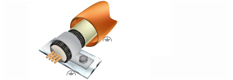
- Shield integration
For discharge purposes, a “good connection” of the shield should be aimed for, i.e. - low impedance/ low resistance → cross-section as large as possible, finely stranded, earth strap if necessary
- short cables
- large-area contact, EMC seal if necessary
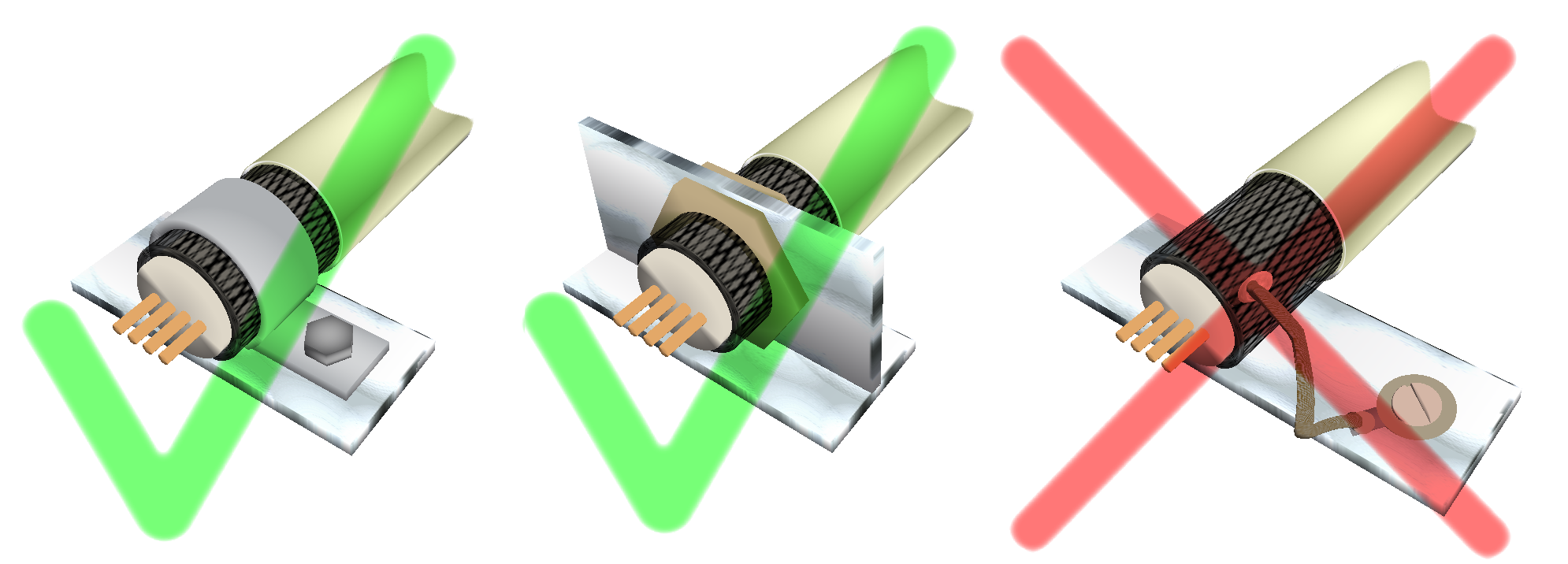
- as 360° comprehensive as possible
- metallic conductive components without dirt, paint, grease, oxide layer
|
|

| - Pig tails (braid twisted at the end or wire attached to the braid) significantly reduce the effectiveness of the shield coupling. In principle, this is not advisable, particularly with regard to the requirements for interference immunity. |
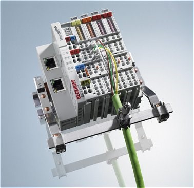
- Beckhoff offers the ZB8500 shield connection system.
- If there is more than 1 conductive connection between 2 devices, hum interference ("earth loop") can occur. Alternating magnetic fields can induce circular currents. This can be done simply by connecting cables/shield connections at both ends between two devices that are located on a common electrically conductive foundation, e.g. the machine structure.
In such cases
However, unilateral separation of the shield can significantly reduce the effectiveness of the shield. A better solution is coupling of the respective shield on one side via a coupling capacitor (C = 10... 100 nF, bipolar). This provides separation for direct current, while currents from HF influence can still be discharged.
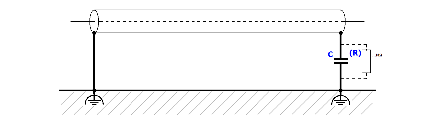
| The coupling capacitor C must have sufficient dielectric strength. If necessary, a resistor R in the MΩ range can be connected in parallel with the capacitor. |
| |
In hazardous areas Note special regulations for hazardous areas! |

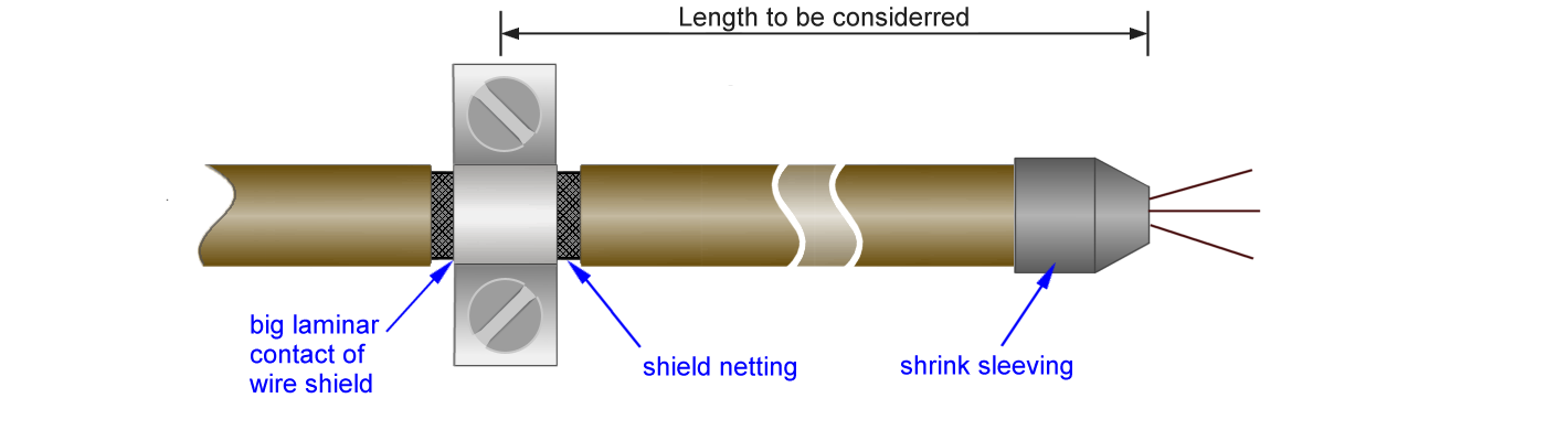
- If the shielded cable continues after the shield contact, the further free cable length under shielding should be no longer than 10 cm. This also applies to cables within control cabinets.
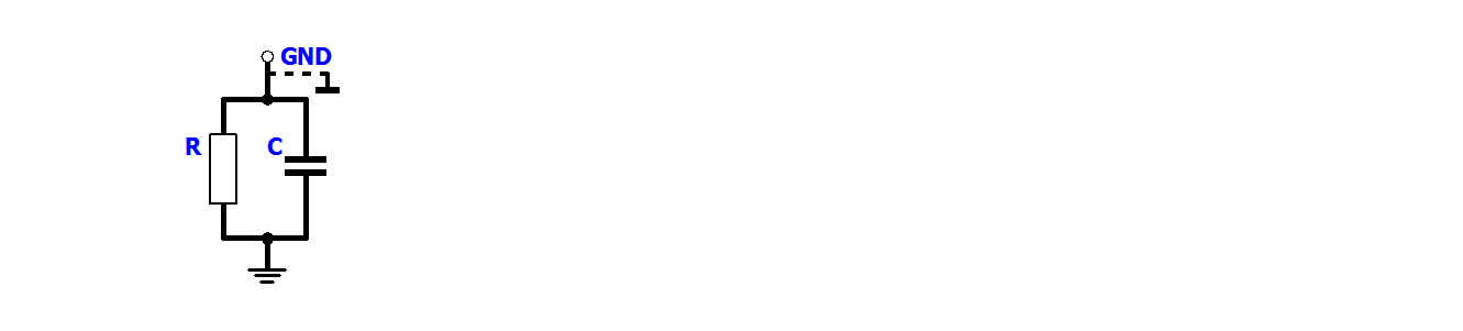
- Manufacturers sometimes equip devices with an RC combination between earth and PE. On the one hand this can achieve good discharge capacity for HF interference, on the other hand the device may not be damaged inadvertently through high leakage currents. Such an RC combination on the device side as connection between earth and PE counts as earth-free coupling.
- A high-resistance resistor prevents excessive leakage currents. The capacitor short-circuits high-frequency peaks with low impedance. A specified dielectric strength applies to the combination.
Good interference protection can be achieved if a shielded cable is laid completely earth-free (only RC connection on both sides). - If a shielded cable has a drain wire, connection of this conductor to the shield coupling only is inadequate. At the cable end the shield and the drain wire should be connected together at the designated shield point.
- Connection of the shielding with sources of interference - only expected outside the control cabinet
- Apply the shielding at the control cabinet entry
- Continuation of the shielding within the control cabinet may not be necessary
- Connection of the shielding with sources of interference - also expected inside the control cabinet
- see: notices on control cabinet design
- The shielding should be opened after the entry into the control cabinet then connected and continued up to the terminal. At the device it should be contacted again (terminal contact or separate shield coupling).
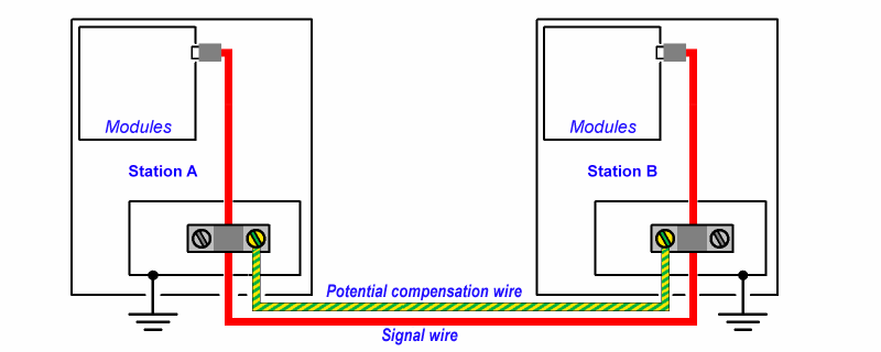
Equalization of potential difference
- If signal or communication lines are run over longer distances, the installation should be checked for potential differences. Example: ribbon conductors in a wind turbine tower. To prevent equalizing currents in the shielding:
- suitable equipotential bonding conductors can be provided
- fiber optic can be used
- buffer amplifiers can be used
- The equipotential bonding conductor should be fine-wired, so that it has a large surface area to ensure effectiveness for high-frequency interference currents. In addition, compliance with the minimum diameters according to IEC 60364-5-54 is required
- copper 6 mm²
- aluminum 16 mm²
- steel 50 mm²
- The earthing system should have a star configuration.
- The PE connection replaces neither HF earthing nor the shielding, but is required for safety reasons.
- Lightning protection may have to be provided.
- Atmospheric influences can lead to significant potential shifts.
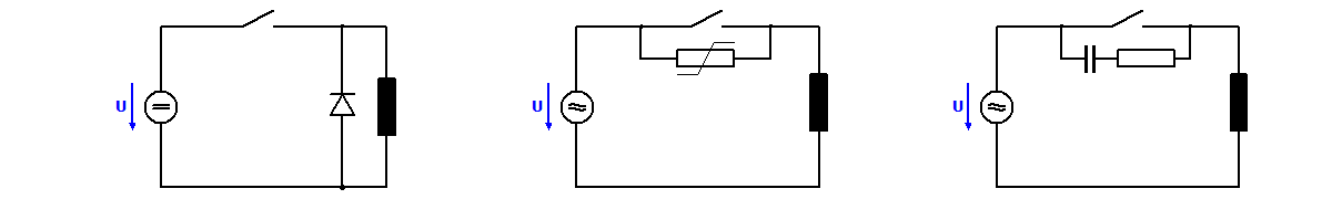
Additional safety measures
- For connected inductors and capacitors protective circuits/extinguishing equipment must be provided on the device side, in order to prevent voltage peaks, unless the connected device already has such a function.
- Filter components against interference emission should be used if necessary, e.g. in the form of current-compensating chokes or toroidal core ferrites
- Pick up the power supply for the measuring equipment in a star shape from the central supply source.
Lay the forward and return conductors next to each other - Thermoelectric effects in the mV range can interfere with analog signals, therefore
- avoid potential differences between different materials
- check the temperature or material, if necessary
Practice-oriented diagnostic methods for system examination
The following section lists some options for checking the effectiveness of shielding measures:
- Visual inspection
- Acoustic inspection (listen for voltage flash-overs)
- Voltage measurement with voltmeter between suspect system points
- Monitoring of voltages on shielding conductors with an oscilloscope that is suitable for high frequencies
- Current measurement of equalizing currents on the shielding cable with a clamp-on ammeter.
The current on the shielding should not exceed a few milliamps (True RMS). - Continuity measurement of the shielding and checking for unacceptable shunt
- Temperature measurement of surge arresters; the contact point will warm up in the presence of high current passage and high contact resistance
- Device-integrated diagnostics such as bus error counters etc.