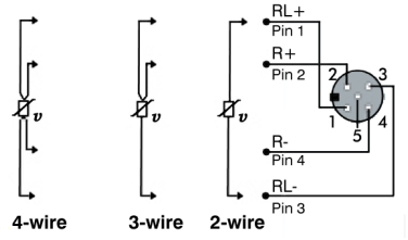
3-wire resistance measurement
- With the 3-wire measurement
- a defined current is initially applied between the contact points RL+ und RL- and the resistance between them is determined on the basis of the voltage drop.
- The same procedure is subsequently carried out at the contact points R+ und RL-.
- The difference between the two measurements is the line resistance of one of the cores of the sensor cable. By knowing the line resistance the resulting measuring error can be compensated.
- The cores of the sensor cable must have the same resistance in order for the method to work.
The box uses the following calculation rule
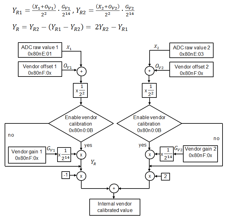
With the values:
| Index in the CoE directory with | |
|---|---|---|
X1: raw value of the 1st measurement | 0x80nE:01 | |
X2: raw value of the 2nd measurement | 0x80nE:03 | |
| Pt100 | Pt1000 |
Gv1: Vendor gain, 1st measurement | 0x80nF:04 | 0x80nF:0A |
Ov1: Vendor offset, 1st measurement | 0x80nF:03 | 0x80nF:09 |
Gv2: Vendor gain, 2nd measurement | 0x80nF:02 | 0x80nF:08 |
Ov2: Vendor offset, 2nd measurement | 0x80nF:01 | 0x80nF:07 |
YR1: Output value in 1/256 Ω | 0x80nE:02 | |
YR2: Output value in 1/256 Ω | 0x80nE:04 | |
YR: Output value in 1/256 Ω | ||
 | Overflow YR1 and YR2 after 16 bits These values are only for fault finding. The registers overflow after 16 bits, i.e. at 65536. |