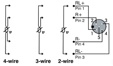
2 and 4-wire resistance measurement
Whether a measurement is executed as a 2 or 4-wire measurement is determined by the connection points at which the measurement takes place. A comparison value is stored in the firmware for both measuring methods.
- With the 2-wire measurement
- a current is applied between the contact points RL+ und RL- and the voltage drop is measured in order to determine the resistance.
- The parasitic line resistance cannot be determined by the box itself, but must be entered as a correction value in the CoE register 0x80n0:1B.
- With the 4-wire measurement
- the sensor current is applied between the contact points RL+ und RL- of the M12 socket and the voltage drop at the contact points R+ and R- is used to measure the resistance.
- The conducting wire is thus not part of the measuring circuit and is not incorporated into the measurement as a source of error.
The box uses the following calculation rule:
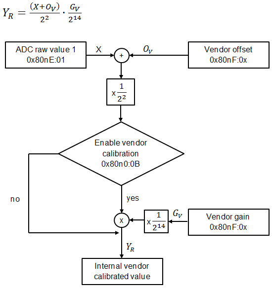
With the values:
| Index in the CoE directory with | |||
|---|---|---|---|---|
X: Raw value | 0x80nE:01 | |||
| Pt100 | Pt1000 | ||
2-wire | 4-wire | 2-wire | 4-wire | |
Gv: Vendor Gain | 0x80nF:04 | 0x80nF:06 | 0x80nF:0A | 0x80nF:0C |
Ov: Vendor Offset | 0x80nF:03 | 0x80nF:05 | 0x80nF:09 | 0x80nF:0B |
YR: Output value in 1/256 Ω | 0x80nE:02 | |||
 | Overflow YR after 16 bits This value is only for fault finding. The register overflows after 16 bits, i.e. at 65536. |