Signal connection
Analog inputs
M12 sockets X01 and X02.
There is one analog input per M12 socket. The input can measure either voltage or current. The measuring ranges can be found in the chapter Technical data.

The sensor is connected via Input+ and Input-. The sensor can optionally be operated/supplied with 24 VDC.
Analog outputs
M12 sockets X03 and X04.
There is one analog output per M12 socket. The output can output either voltage or current. The measuring ranges can be found in the chapter Technical data.

The actuator is connected via output +/- and output GND. The actuator can optionally be operated/supplied with 24 VDC.
Status LEDs at M12 connections (inputs and outputs)
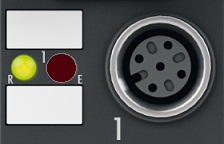
Status LEDs at M12 connections 1 and 2 (inputs) | |||
|---|---|---|---|
Connection | LED | Display | Meaning |
M12 socket 1 and 2 | R left | off | No data transfer to the A/D converter |
green | Data transfer to A/D converter | ||
E right | off | Function OK | |
red | Error: Open circuit or measured value outside of the measuring range (smaller than 3.5 mA/-11 V or larger than 21 mA/11 V) | ||
Correct function is indicated if the green Run LED is on and the red Error LED is off.
Status LEDs at M12 connections 3 and 4 (outputs) | |||
|---|---|---|---|
Connection | LED | Display | Meaning |
M12 socket 3 and 4 | R left | off | No data transfer to the D/A converter |
green | Data transfer to the D/A converter | ||