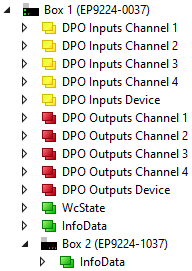
Process image
The EtherCAT P ports are labeled "Channel 1" to "Channel 4" in the process image. The following table shows the correlation between the designations in the process image and the designations of the EtherCAT P ports:
Designation in the process image | EtherCAT P port |
|---|---|
Channel 1 | X52 |
Channel 2 | X53 |
Channel 3 | X54 |
Channel 4 | X55 |
| DPO Inputs Channel n DPO Inputs Device DPO Outputs Channel n DPO Outputs Device WcState and InfoData EP9224-1037 |
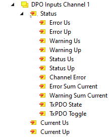
DPO Inputs Channel 1 to 4
Status bits of the individual channels.
| Error Us: US was switched off due to overload. Error Up: UP was switched off due to overload. Warning Us: The output current US currently exceeds the nominal current (CoE parameter 80n0:12). Warning Up: The output current US currently exceeds the nominal current (CoE parameter 80n0:13). Status Us: Switching status (on/off) of the output voltage US. Status Up: Switching status (on/off) of the output voltage UP. Channel Error: "Error Us" or "Error Up" is TRUE. Error Sum Current: The channel was switched off due to sum overcurrent. Warning Sum Current: The sum current IS + IP of the channel currently exceeds the nominal sum current (CoE parameter 80n0:14). Current Us, Current Up: 16-bit measured values of the current output currents. |
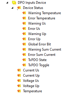
DPO Inputs Device
Status bits for the entire device.
| Temperature Warning: The internal temperature exceeds the warning threshold. Temperature Error: The internal temperature has exceeded the error threshold. The output channels have been switched off. US Warning, UP Warning: Undervoltage warning. The respective input voltage is currently below the warning threshold value Uwarn. Us Error, Up Error: Undervoltage switch-off. The respective input voltage has fallen below the error threshold value Uerr. Global Error Bit: There is at least one error message. Sum Current Warning: The input sum current IS + IP currently exceeds the nominal sum current (CoE parameter F80E:12). Error Sum Current: All output voltages were switched off due to sum overcurrent. Current Us: Current US input current at supply voltage input X70. Current Up: Current UP input current at supply voltage input X70. Voltage Us: Current value of the supply voltage US in 1/10V Voltage Up: Current value of the supply voltage UP in 1/10V Temperature: Current internal temperature of the device. |
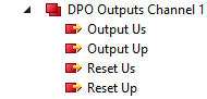
DPO Outputs Channel 1 to 4
Output data for the individual channels.
| Output US, Output UP: Switches the respective output voltage on or off. Reset US, Reset UP: Reset the error state of the respective output voltage. |
DPO Outputs Device
Output data for the entire device.
| Enable Control Via Fieldbus:
Global Reset: Reset the error state of the device and all channels. |