Tacho analysis
Tacho analysis refers to velocity or frequency logging for two digital sensors mounted on one shaft (single-shaft mode) or on two shafts (dual-shaft mode).
In single-shaft mode a plausibility check can be run for the two sensors (e.g. velocity deviation of the two sensors).
The targets (sensor markings) should show a 90° overlapping signal when triggered. The minimum ON of OFF time must not be less than 0.2ms, otherwise detection is not possible due to the sampling frequency.
The number of targets on the axis can be set in CoE object 0x80x0:11. In this way slower velocity/speed detection with many targets or high velocity with few targets can be achieved.
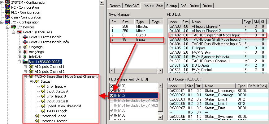
Mode selection via the PDOs
The different modes are activated via the PDO assignment.
Single-shaft mode
The input PDO 0x1A02 activates the corresponding setting. The output data are always set.
Process data
Value | Description |
|---|---|
Error Input A | The measured velocity/frequency is lower than that of track B, or it is 0 (sensor faulty) |
Input Status A | Status of input A |
Error Input B | The measured velocity/frequency is lower than that of track A, or it is 0 (sensor faulty) |
Input Status B | Status of input B |
Speed below threshold | The velocity is lower than the limit in CoE 0x8020:12 Rotational Speed Threshold or = 0 |
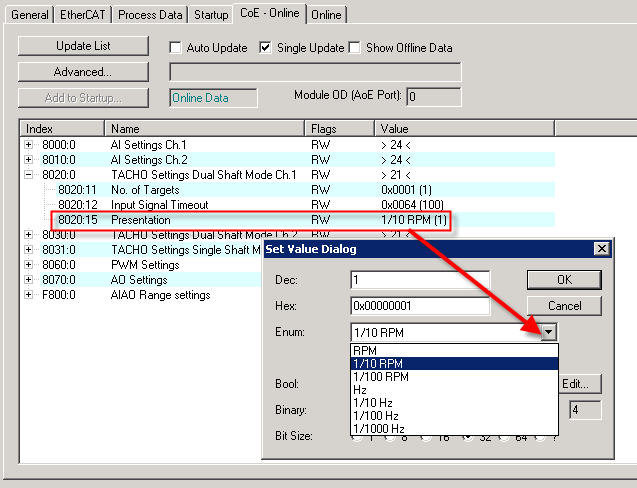
Rotational Speed | Rotational speed and frequency, shown as a function of CoE object 0x80x0:15 |
Rotation Direction | 0: rising edge of input A occurs before rising edge of input B |
Display of the rotational speed
Dual Shaft Mode
The input PDOs 0x1A03 and 0x1A04 activate the two dual-shaft process data. The output data are always set.
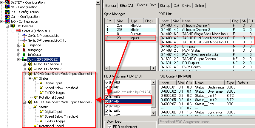
Process data (settings for the second channel equivalent)
Value | Description |
|---|---|
Digital input | Status of input |
Speed below threshold | The velocity is lower than the limit in CoE 0x8020:12 or = 0 |
Rotational Speed | Rotational speed and frequency, shown as a function of CoE object 0x80x0:15 |
Display of the rotational speed
see single-shaft mode
CoE settings
The behavior of the tacho inputs is set via the CoE objects.
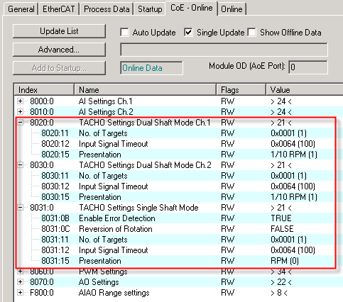
The following settings apply to all channels:
CoE | Value | Description |
|---|---|---|
80xx:12 | Input Signal Timeout | The process record <Speed Below Threshold> is set after x msec without signal change at the input. |
The following settings are only available in single-shaft mode
CoE objects for tacho settings (0x8020 and 0x8030)
CoE | Value | Description |
|---|---|---|
80x0:0B | Enable Error Detection | Enable/disable error display |
80x0:0C | Reversion of rotation | Reversion of rotation display in Rotation direction |
80x0:11 | No. of Targets | Number of "cams" on the shaft/axis |
80x0:12 | Rotational Speed Threshold | Limit value below which the corresponding status bit is set |
80x0:15 | Presentation | Display of the measured value in RPM, Hz, … |