Process image
The size of the process image can be set from firmware 04 onwards.
This chapter describes the process image in the factory setting. It contains 22 bytes of receive data and 22 bytes of send data.
Among other things, the size of the process image determines the maximum continuous data transfer rate. If your application requires a higher data transfer rate, you can set the size of the process image from firmware 04 onwards.
Complete process image
|
|
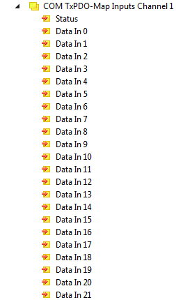
COM TxPDO-Map Inputs
The following figure shows an example of the process data object for serial channel 1. The process data object for channel 2 is structured in exactly the same way.
|
|
Status Status word for receive data.
Data In [n] The input variables „Data In 0“ .. „Data In 22“ each contain one byte of receive data (USINT). „Data In 0“ contains the first-received byte. |
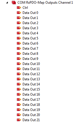
COM RxPDO-Map Outputs
The following figure shows an example of the process data object for serial channel 1. The process data object for channel 2 is structured in exactly the same way.
|
|
Ctrl Control word for transmit data.
Data Out [n] The output variables "Data Out 0" .. "Data Out 22" can each be filled with one byte of send data. The content of "Data Out 0" is transmitted first. |