Commissioning
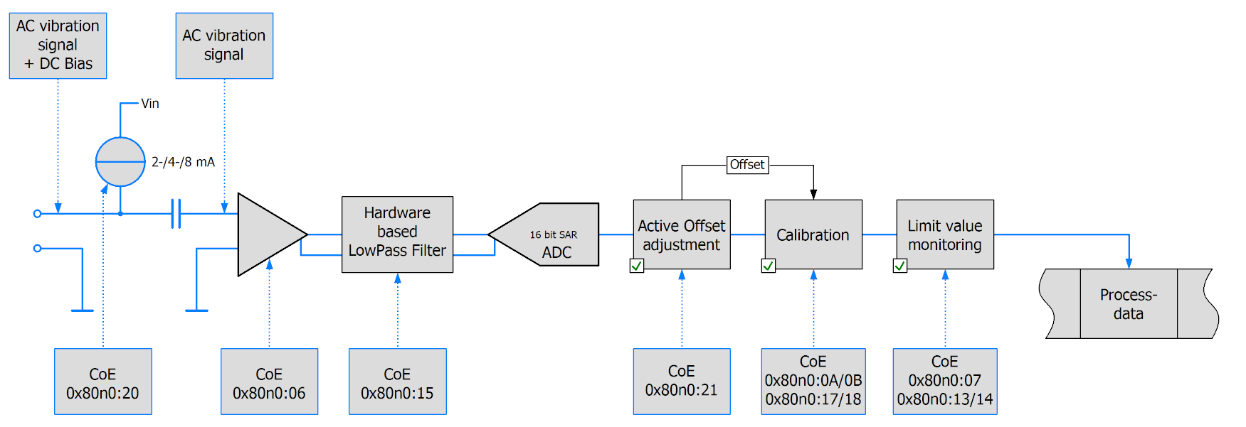
The data flow through of the terminal's channel is recorded below. The elements involved are described in detail in this chapter.
Note: The sampling rate in the ADC and the low-pass filter can be set independently of each other. For example, the filter can be set to half the sampling rate or to the next possible setting if required for the application.
Determination of the desired sampling rate
The necessary/desired sampling rate results from the selected cycle time and the set oversampling factor.
Automatic setting of the terminal/box by the selection of the sampling rate alone is not possible.
Maximum values: 50-fold oversampling, 50 kSP/s, cycle time 10 ms
Configurations that demand sampling times not divisible by 500 ns are not supported.
Setting the sampling rate
1. Select the terminal/box in the TwinCAT tree
2. Select the “DC/Oversampling” tab
3. Select the operating mode (1/2-channel)
4. “Sync Unit Cycle Time” is indicated; on the basis of the above table…
5. Select the oversampling factor. The “Sample Cycle Time (µs)” indicates the reciprocal value of the sampling rate. The SM automatically activates all process data entries thereafter.
 | Loading the configuration data (ESI) from the terminal If the online description is used, the DC/Oversampling dialog is not displayed in the TwinCAT System Manager. |
Application with external masters
The oversampling function can also be activated manually: The oversampling factor should be specified depending on the required sampling rate and cycle time.
For each required channel the status word and the corresponding number of samples have to be entered in object 0x1C13. Activate PDOs "Next Sync1 Time" and/or "Sample Counter", if necessary. To this end, initially set subindex 0 to 0 and at the end to the number of entered values.
The sync interrupts should be parameterized as follows: Sync0: CycleTime/Oversampling Factor, set Enable; Sync1 Cycle Unit Cycle, set Enable.
The master must support Distributed Clocks.
Selection of the process data
No longer necessary with TwinCAT.
Filter
Each channel has a parameterizable 5th order filter with Butterworth characteristic with upstream and downstream anti-aliasing filters that are parameterized automatically. The whole filter stage is based on hardware. There are no software filters (except for the active offset setting described below). When the limit frequency is set to 10 Hz (0), an additional amplification factor 20 is activated automatically.
The analog input filters can be set via the CoE objects 0x80n0:15 (channel 1/2). It is not possible to switch off the filters.
The characteristic of the filter stage is adjustable:
0: 10 Hz, Gain 20
1: 100 Hz
2: 500 Hz
3: 1000 Hz
4: 5000 Hz
5: 10000 Hz
6: 25000 Hz
7: 2000 Hz (from firmware 11)
| Setting the filters The filters must be configured separately for both channels. |
Active offset setting
The function "Active offset adjustment" calculates the long-term average of the values. The calculated offset value is used instead of the set "user" and "vendor calibration offset" entries. At least one function, "user" or "vendor calibration", must be activated
The calculation of the average value is configurable:
Level 1: b = 1/4096
Level 2: b = 1/8192
Level 3: b = 1/16384
Level 4: b = 1/32768
Level 5: b = 1/65536
Level 6: b = 1/131072 (128 k)
Level 7: b = 1/262144 (256 k)
Level 8: b = 1/524288 (512 k).
Calibration
The input values can be calibrated by means of manufacturer or user values:
Fig. 5: Data flow
Vendor calibration, index 0x80n0:0B
The vendor calibration is enabled via index 0x80n0:0B. Parameterization takes place via the indices
- 0x80nF:01 offset (manufacturer compensation)
- 0x80nF:02 gain (manufacturer compensation)
|
YH = (XADC - BK) * AK |
Measured value following manufacturer calibration (corresponds to XADC if index 0x80n0:0B is inactive) |
User calibration, index 0x80n0:0A
The user calibration is enabled via index 0x80n0:0A. Parameterization takes place via the indices
- 0x80n0:17 User calibration offset
- 0x80n0:18 User gain compensation
|
YA = (YH - BW) * AW |
Measured value following user calibration (corresponds to YH if index 0x80n0:0A is inactive) |
Active offset adjustment
If the function "Active offset adjustment" is active the offset values are not used. Instead, a dynamically calculated offset is subtracted.
Example interpretation
Sample: A sensor with a sensitivity S of 100 mV / g (10.2 mV/(m/s^2) ) is connected to a synchronized EL3632/EP3632 (15-bit resolution + sign, +/- 5 V). In the process data an amplitude of 1507 is measured.
a = YA * 5 V / ( 2^15 * S ) | Conversion of process data value YA to acceleration a. |
YA = 2^15 / 5 V * S * a | Conversion of acceleration g to process data value YA. |
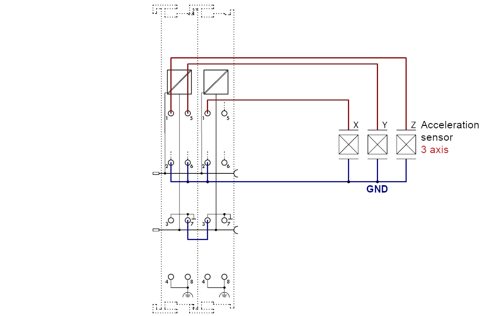
Sensor connection
The supply current for the sensors is configurable. With 8 mA the vertical (standard) installation position of the terminal must be ensured. The smallest possible supply current should be set, depending on the sensor and cable length.
After switching on the 24 V supply voltage or connecting the sensor, a leakage current forms due to the input capacity on the high-pass filter. This current is based on the physical properties of electrolytic capacitors and is technically impossible to prevent. This current stabilizes at a constant value within a few minutes, and during the measurement it generates a constant offset of typically a few mV within the specified tolerance range. If this offset should prove to be disturbing when analyzing the measurement, it can be permanently and automatically subtracted out by activating the "Active offset adjustment" (object 0x80n0:21).
A shielded (simple or multiple) sensor cable must be used. The shield should be connected directly at the shield connections of the terminal.
The red error LED comes on and the error bit is set in the event of an open circuit or if no sensor is connected. If only the first channel is activated, the red LED for the second channel is disabled in SAFEOP and OP state.
Multi-channel IEPE sensors with a common GND can be connected to the EL3632 if the GND and AGND connection points are connected via an external bridge:
| Unused inputs Unused inputs must not be short-circuited. |
Measuring error
Measuring error < ±0,5% (DC; relative to full scale value), taking into account the Butterworth characteristic.