Process data
This section describes the individual PDOs and their content. A PDO (Process Data Object) is a unit on cyclically transmitted process values. Such a unit can be an individual variable (e.g. the weight as a 32-bit value) or a group/structure of variables. The individual PDOs can be activated or deactivated separately in the TwinCAT System Manager. The "Process data" tab is used for this (visible only if the box is selected on the left). A change in the composition of the process data in the TwinCAT System Manager becomes effective only after restarting the EtherCAT system.
The EP3356-0022 can be used in 2 basic operating modes
- 1-channel strain gauge evaluation (strain gauge, balance beam, load cell): Here, both analog input voltages are measured internally, they are calculated locally according to the internal settings in the box and the resulting load value is output to the controller as a cyclic process value. The box is to be regarded as a 1-channel box. The load value can be output as an integer or as a float/real representation.
- 2-channel voltage measurement: Both analog input voltages are output directly as process values; no load calculation takes place. The value and status information can be output for each channel.
The basic operating mode of the EP3356-0022 is determined by the selection of the process data (PDO). The procedure for the selection of the process data can be found in chapter Selection of the process data.
Predefined PDO Assignment
In order to simplify the configuration, typical configuration combinations of process data are stored in the device description. The predefined configurations can be selected in the process data overview. Therefore the function is available only if the ESI/XML files are saved in the system.
The following combinations are possible:
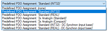
- Standard (INT32): [Default setting] load calculation; 32-bit integer load value as final value according to the calculation specifications in the CoE, no further conversion necessary in the PLC
- Standard (REAL): Load calculation; 32-bit floating-point load value as final value according to the calculation specifications in the CoE, no further conversion necessary in the PLC
- 2x AnalogIn (Standard): 2-channel voltage measurement, 32-bit integer voltage value with additional information (under-range, over-range, error, TxPdoToggle)
- 2x AnalogIn (Compact): 2-channel voltage measurement, 32-bit integer voltage value only
Default process image
The default process image is standard (INT32).
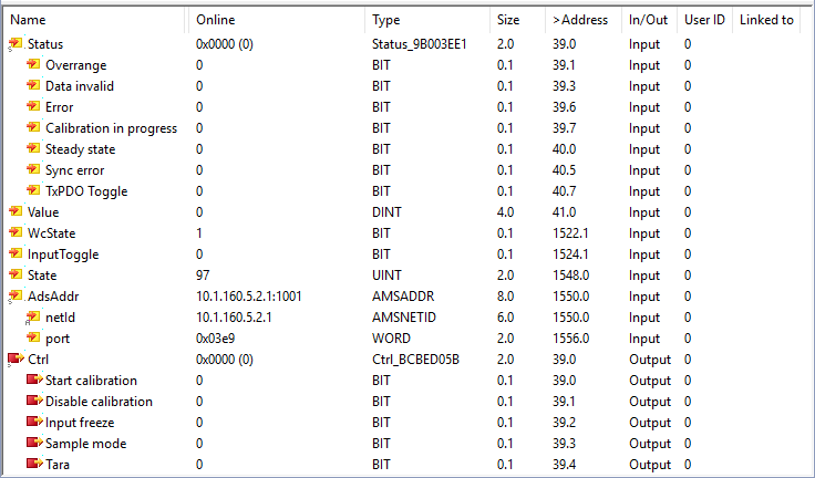
Function of the variables
Variable: Status
Meaning: The status word (SW) is located in the input process image, and is transmitted from box to the controller.
Bit | SW. 15 | SW. 14 | SW. 13 | SW.12 | SW. 11 | SW. 10 | SW. 9 | SW. 8 | SW. 7 | SW. 6 | SW. 5 | SW. 4 | SW. 3 | SW. 2 | SW. 1 | SW. 0 |
Name | TxPDO Toggle | - | Sync Error | - | - | - | - | Steady State | Calibration in progress | Error | - | - | Data invalid | - | Overrange | - |
Meaning | Toggles 0→1->0 with each updated data set | - | Synchronisation error |
| Calibration in progress | Collective error display | - | - | Input data are invalid | - | Measuring range exceeded | - | ||||
Variable: Value
Meaning: Calculated 32-bit DINT load value in unit [1], with sign
Variable: Value (Real)
Meaning: Calculated 32-bit fixed point REAL load value with mantissa and exponent in unit [1]
The format matches the REAL format of IEC 61131-3, which in turn is based on the REAL format of IEC 559. A REAL number (single precision) is defined as follows (See also Beckhoff InfoSys: TwinCAT PLC Control: standard data types). In accordance with IEC 61131 this 32-bit variable can be directly linked with a FLOAT variable of the PLC.
Bitposition (from the left) | 1 | 8 | 23 (+1 „hidden bit“, see IE559) |
Function | Sign | Exponent | Mantissa |
Variable: WcState
Meaning: Cyclic diagnostic variable; „0“ indicates correct data transmission
Variable: Status
Meaning: State of the EtherCAT device; State.3 = TRUE indicates correct operation in OP
Variable: AdsAddr
Meaning: AmsNet address of the EtherCAT device from AmsNetId (in this case: 192.168.0.20.5.1) and port (in this case: 1003)
Variable: Ctrl
Meaning: The control word (CW) is located in the output process image, and is transmitted from the controller to the box.
Bit | CW. 15 | CW. 14 | CW. 13 | CW. 12 | CW. 11 | CW. 10 | CW. 9 | CW. 8 | CW. 7 | CW. 6 | CW. 5 | CW. 4 | CW. 3 | CW. 2 | CW. 1 | CW. 0 |
Name | - | Tara | Sample Mode | Input Freeze | Disable Calibration | Start Calibration | ||||||||||
Meaning | - | starts tare | mode switching (EL3356-0010 and EP3356-0022only) | stops the measurement | Switches the automatic self-calibration off | Starts the self-calibration immediately | ||||||||||
See also the example program for the dissection of the Status and CTRL variable.
Variants (Predefined PDO)
Fixed-point representation of the load
The display of the load value can also be converted already in the box into a point representation. To do this the input PDOs are to be changed as follows:
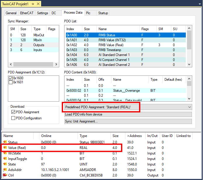
Variable: Value (Real)
Meaning: Calculated 32-bit fixed point REAL load value with mantissa and exponent in unit [1]
The format matches the REAL format of IEC 61131-3, which in turn is based on the REAL format of IEC 559. A REAL number (single precision) is defined as follows (See also Beckhoff InfoSys: TwinCAT PLC Control: standard data types). This 32-bit variable can be linked directly with a FLOAT variable of the PLC according to IEC61131.
Bit position (from left) | 1 | 8 | 23 (+1 „hidden bit“, see IEC 559) |
Function | Sign | Exponent | Mantissa |
Voltage measurement
The EP3356-0022 can also be used as a 2-channel analog input box for voltage measurement, see Notes.
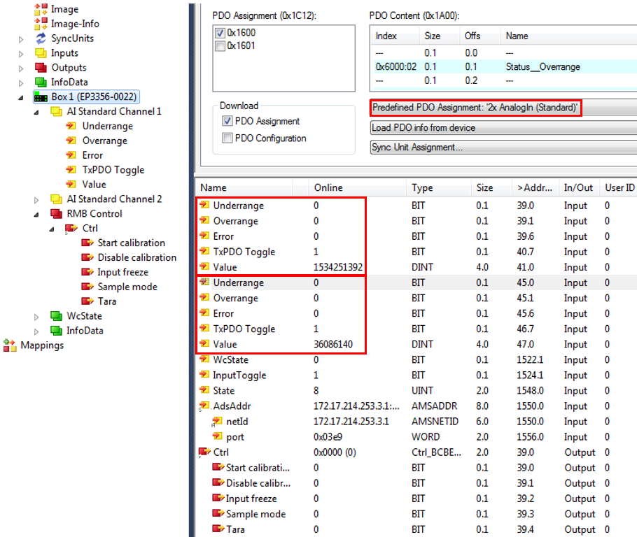
Variable | Meaning |
|---|---|
Underrange | Measurement is below range |
Overrange | Measuring range exceeded |
Error | Collective error display |
TxPDO Toggle | Toggles 0→1→0 with each updated data set |
Value | Right-justified voltage value over the respective measuring range (Range of values 0x80.00.00.00…0…0x7F.FF.FF.FF) Channel 1: supply voltage Channel 2: bridge voltage |
Distributed Clocks
In DC mode (Distributed Clocks) the process data x1A03 Timestamp must be activated.
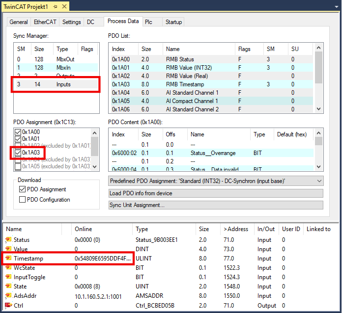
Also, the variables DcOutputShift and DcInputShift are displayed in the process data in DC mode. Upon activation of the configuration these are calculated once in the unit [ns] on the basis of the set EtherCAT cycle time (observe assigned task!) and DC shift times from the EtherCAT master settings. In the InputBased operating mode, DcInputShift indicates by how many nanoseconds [ns] before or after the global Sync the box determines your process data. For further information on this, see the EtherCAT system description.
Since the EP3356-0022 is not DC-triggered but determines the timestamp itself, these values have no meaning in the EP3356-0022.
Sync Manager (SM)
PDO Assignment
Inputs: SM3, PDO Assignment 0x1C13
Index | Index of excluded PDOs | Size (byte.bit) | Name | PDO content |
|---|---|---|---|---|
0x1A00 (default) | - | 2.0 | RMB Status (Resistor Measurement Bridge) | 0x6000:02 - Overrange |
0x1A01 (default) | 0x1A02 | 4.0 | RMB Value (INT 32) | 0x6000:11 - Value |
0x1A02 | 0x1A01 | 4.0 | RMB Value (Real) | 0x6000:12 - Value |
0x1A03 | 0x1A04 | 8.0 | RMB Timestamp | 0x6000:13 - Value |
0x1A04 | 0x1A00 | 6.0 | AI Standard Channel 1 (Analog Input) | 0x6010:01 - Underrange |
0x1A05 | 0x1A00 | 4.0 | AI Standard Channel 1 (Analog Input) | 0x6010:11 - Value |
0x1A06 | 0x1A00 | 6.0 | AI Standard Channel 2 (Analog Input) | 0x6020:01 - Underrange |
0x1A07 | 0x1A00 | 4.0 | AI Standard Channel 2 (Analog Input) | 0x6020:11 - Value |