EP2817-0008 - Process image
DIG Diag Inputs Channel 1
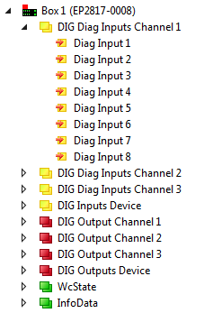
Under DIG Diag Inputs Channel 1 - 3 you will find the diagnostic inputs of the 8 digital outputs (DIG Outputs Channel 1 - 3) of the module.
|
Data types
|
 DIG Diag Inputs Channel 1
 Diag Input n: BIT
Diag Input n
Indicates an error at output n, i.e. an output switched ON is OFF, or an output switched OFF is ON
DIG Inputs Device
You will find the module's status inputs under DIG Inputs Device.
|
Data types
|
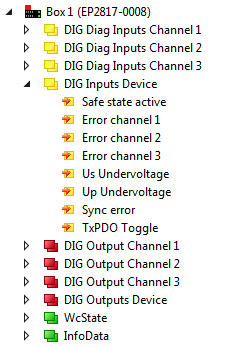
Safe state active
Indicates whether the safe state has been assumed. The display only works if the network transmits process input data, i.e. in the network states Pre-Operational (PRE-OP) and Operational (OP), but not in the network state INIT.
Error channel n
Indicates an error on channel n.
Us Undervoltage
Indicates that the voltage Us < approx. 18V.
Up Undervoltage
Indicates that the voltage Up < approx. 18V.
Sync Error
See EtherCAT system documentation.
TxPDO Toggle
See EtherCAT system documentation.
DIG Outputs Channel n
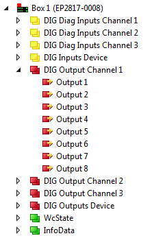
Under DIG Outputs Channel 1 - 3 you will find 8 digital outputs of each module.
|
Data types
|
 DIG Output Channel 1
 Output n: BIT
The assignment is always made in pairs on the left and right side of the D-SUB connector in order to systematically connect double-switching valves.
|
Type |
Output 2 |
Output 4 |
Output 6 |
Output 8 |
Output 10 |
Output 12 |
Output 14 |
Output 16 |
Output 18 |
Output 20 |
Output 22 |
Output 24 |
|
|
Pin |
14 |
15 |
16 |
17 |
18 |
19 |
20 |
21 |
22 |
23 |
24 |
25 |
|
|
Type |
Output 1 |
Output 3 |
Output 5 |
Output 7 |
Output 9 |
Output 11 |
Output 13 |
Output 15 |
Output 17 |
Output 19 |
Output 21 |
Output 23 |
GND |
|
Pin |
1 |
2 |
3 |
4 |
5 |
6 |
7 |
8 |
9 |
10 |
11 |
12 |
13 |
DIG Outputs Device
You will find the module's control outputs under DIG Outputs Device.
|
Data types
|
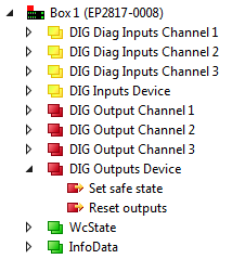
Set safe state
Sets the module to the safe state.
Reset outputs
Resets the error bits "Error channel X" of the module. The outputs are reactivated.