EL6751 – Bus node diagnostics
The CANopen fieldbus card EL6751 has a comprehensive range of diagnostic options for connected network nodes.
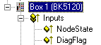 Fig.139: Diagnosis of inputs in the TwinCAT tree
For each CANopen fieldbus node there is a node state input variable, which signals the status of the current slave during the runtime and can be linked, for example with the PLC.
Node State (Box-State)
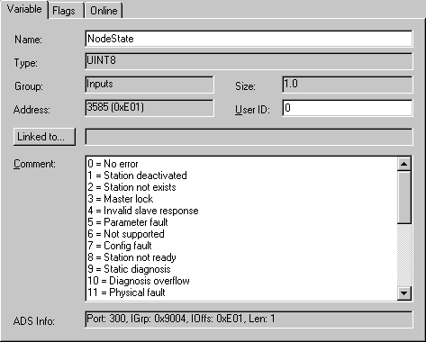 Fig.140: "Variable" tab
|
Node State |
Meaning |
Explanation |
|---|---|---|
|
0 = 0x00 |
No error |
Bus node is operational, communication is running correctly |
|
1 = 0x01 |
Node deactivated |
The node is subject to one or more of the following errors:
Node has been stopped, because "Manual restart" following a node failure has been selected. |
|
2 = 0x02 |
Node not found |
Node not found: no answer to SDO read access to object 0x1000 at the expected node address. Check the following at the node: what node address is set, and what baud rate. Check network (terminating resistors, connectors, bus length, crossed wiring etc.) |
|
4 = 0x04 |
SDO syntax error at StartUp |
Error during SDO write access: SDO abort by node. See the "Diag" tab for details. |
|
5 = 0x05 |
SDO data mismatch at StartUp |
Expected data does not agree with that read via SDO (e.g. device profile and/or additional info do not agree with object 0x1000). Can also occur if the value to be written (e.g. PDO COB-ID) is read back due to refusal of write access, and does not agree. See the "Diag" tab for details. |
|
8 = 0x08 |
Node StartUp in progress |
Node was found and has been started. |
|
11 = 0x0B |
EL6751Bus-OFF |
CAN chip has entered the "Bus-OFF" state: transmit error counter is running |
|
12 = 0x0C |
Pre-Operational |
Node has gone pre-operational (on its own account). |
|
13 = 0x0D |
Severe bus fault |
General firmware error |
|
14 = 0x0E |
Guarding: toggle error |
Guarding error: Toggle bit has not changed |
|
20 = 0x14 |
TxPDO too short |
Received TxPDO shorter than expected |
|
22 = 0x16 |
Expected TxPDO is missing |
|
|
23 = 0x17 |
Node is Operational but not all TxPDOs were received |
Node has been started, but at least one TxPDO has not yet been received from the node. Possible causes (e.g.):
|
DiagFlag
Shows whether the box diagnostic information has changed.
Reading the Diagnostic Data via ADS
CANopen emergencies and other diagnostic data can be read out via ADS read (new data present as soon as you see the DiagFlag). The ADS Net-ID of the EL6751 must be entered for this. Other ADS parameters:
Port: 200
IndexGroup: Lo-Word = 0xF180, Hi-Word = Node-Number.
IndexOffset: See below
Length: See below
If more than 26 bytes of diagnostic data have been read out the emergency memory is reset. The DiagFlag is reset as soon as at least 108 bytes have been read starting from offset 0. Alternatively, the flag is reset after each of read access, if IndexGroup 0xF181 (instead of 0xF180) is used for the read.
The diagnostic data have the following definitions:
|
Offset 0,1: |
Bit 1: |
Boot up message not received or incorrect |
|
Bit 2: |
Emergency-Overflow | |
|
Bit 0, Bit 3-15: |
reserved | |
|
Offset 2,3: |
Bit 0-14: |
TX-PDO (i+1) received |
|
Bit 15: |
All TX PDOs 16-n received | |
|
Offset 4,5: |
Bit 0-4: |
1: Incorrect TX PDO length |
|
|
2: Synchronous TX PDO absent | |
|
|
3: Node signaling PRE-OPERATIONAL | |
|
|
4: Event timer timed out for TX PDO | |
|
|
5: No response and guarding is activated | |
|
|
6: Toggling missed several times and guarding activated | |
|
Bit 5-15: |
Associated COB ID | |
|
Offset 6: |
Bit 0-7: |
1: Incorrect value during SDO upload |
|
|
2: Incorrect length during SDO upload | |
|
|
3: Abort during SDO up/download | |
|
|
4: Incorrect date during a boot-up message | |
|
|
5: Timeout while waiting for a boot-up message | |
|
Offset 7: |
Bit 0-7: |
2: Incorrect SDO command specifier |
|
|
3: SDO toggle bit has not changed | |
|
|
4: SDO length too great | |
|
|
5: SDO-Abort | |
|
|
6: SDO-Timeout | |
|
Offset 8,9 |
Bit 0-7: |
SDO up/download index |
|
Offset 10: |
Bit 0-7: |
SDO up/download sub-index |
|
Offset 11: |
Bit 0-7: |
reserved |
|
Offset 12: |
Bit 0-7: |
Abort errorClass |
|
Offset 13: |
Bit 0-7: |
Abort errorCode |
|
Offset 14,15: |
Bit 0-15: |
Abort additionalCode |
|
Offset 16-19: |
|
Read value (if offset 6 = 1) |
|
Offset 20-23: |
|
Expected value (if offset 6 = 1) |
|
Offset 24-25: |
|
Number of consecutive emergencies |
|
Offset 26 - n: |
|
Emergencies (8 bytes each) |