Quick start
|
Table of contents |
|---|
EL3692 default setting
The default state for both EL3692 channels is
- CoE mode (parameter settings via CoE)
- alternating measuring mode
- 4-wire mode
- Autorange for the measuring ranges
- Process data: fixpoint and float
- Filter setting 10 Hz (approx. 100 ms conversion time)
- Delay time 10 (200 or 500 ms depending on the measuring range)
 | Time behavior in Autorange mode In standard measuring mode the EL3692 keeps switching between the two channels. Depending on the connected measuring object significant charging effects may occur, which may not be completed within the specified measuring time. In Autorange mode, with significant changes in resistance and associated changes in measuring range, this may result in the correct measuring range not being reached, which would impair the measuring accuracy. |
Step-by-step instructions
Proceed as follows for commissioning with the above-mentioned settings:
- Install the EL3692 as described in section Installation and wiring.
- Activate the EtherCAT master and start the terminal in OP state. In the input variables the EL3692 must supply state=OP and WC=0.
- Connect the resistance in 2-wire or 4-wire mode according to the figure below
- In TwinCAT the EL3692 appears as follows (channel 1 red grouped, channel 2 blue grouped):
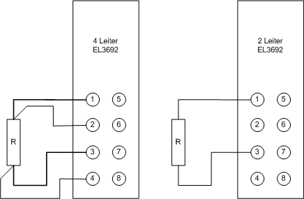 Fig.138: Connection examples
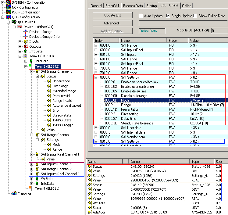 Fig.139: EL3692 representation in the TwinCAT System Manager
- The EL3692 provides the following outputs for each channel:
- SAI Inputs: current status
- SAI Inputs: current measured value 32 bit integer, measuring range-dependent
- SAI Range:: current range (automatic measuring range selection)
- SAI Inputs Real: current measured value 32 bit PLC fixed-point float, measuring range-independent, scaled representation
Please note the information relating to the process data.
5. for 2-wire measurement: In CoE entry x80n0:0D set the mode to 2 (n stands for the channel: 0 = channel 1, 1 = channel 2).
If necessary the EL3692 can be reset to the factory settings via a CoE reset.
| Measured value display The EL3692 can output the current channel-based measured value depending on the PDO option "Predefined PDO assignment" in 2 different ways. As "fixpoint" and "float". See following explanation: |
- as 32 bit integer, measuring range dependent value, with 24 bit content "fixpoint".
Explanation:
The 9 measuring ranges of the EL3692 are named after their recommended range of use e.g. 1 ... 10 Ω, but they all measure down to 0 Ohm. The value range of Value thus extends over x0 ... x00 7F FF FF for each measurement range, with "x0 = 0 ohms" and "x00 7F FF FF ≈ nominal full scale".
However, the nominal measuring range is exceeded by up to 10% in autorange mode to ensure measuring range switching, so-called "extended measuring range".
The information in the status must be observed.
In the following an example for the measuring range "1 ... 10 Ω":
Input resistance |
| 32-bit value | Interpretation | Status bits |
|---|---|---|---|---|
0 Ω |
| x00 00 00 00 | 0 | Extended Range = 0 Overrange = 0 |
10 Ω | Nominal measuring range end value | x00 7F FF FF | 8.388.607 | extended range = 1 "extended measuring range" Overrange = 0 |
10 .. 11 Ω | extended measuring range |
|
| Extended Range = 1 Overrange = 0 |
> 11 Ω |
| x00 8C CC CB | 9.227.467 | Extended Range = 0 Overrange = 1 |
Please note that the relative measurement error is very large at the lower end of the measuring range. When measuring in the range < 10% of the nominal measuring range end value, the next lower measuring range should therefore be used. The autorange function works accordingly.
- as 32-bit fixed-point float-value with mantissa and exponent, measuring range-independent "float"
Explanation:
This 32-bit variable can be linked directly with a FLOAT variable of the PLC according to IEC61131. The conversion takes place in the EL3692; no measuring range-dependent conversion by the user is required.
See additional information on page Process data
6. You have to check the correct operation of the range change function in the autorange opration mode for all test specimens. This is mandatory in the special case, if test specimens with very different resistance/capacity/inductive values are connected to channel 1 and 2 (> 3 measuring ranges). An unoccupied channel will measure in the measuring range 7 (1 MΩ .. 10 MΩ).
This can be compensated channel-wise by the extension of the delay time (CoE 0x80n0:31), if the automatic setting is not sufficient. The delay time should be increased stepwise for the channel, which has not the optimal range setting.
7. During the operation, the channel-wise process data value has to be verified by checking of the state variables Error, DataInvalid and SteadyState.
For further configuration in TwinCAT please refer to sections Process data and Important CoE entries.