Quick start
Parameterizing the terminal
- If provided, the current ESI (XML file) EL2595-0000-xxxx is to be installed in TwinCAT (usually under C:\TwinCAT\IO\EtherCAT\).
Otherwise, please download the latest ESI from the Beckhoff-Website. - If necessary, a firmware update is to be carried out. Check then in the online CoE.
- Following the firmware update you are urgently recommended to carry out a "Restore default parameter" in the CoE: enter "0x64616F6C" in CoE index 0x1011:01
- The key data of the intended LED must be determined:
- Intended forward current (operating current) [mA]
- Required forward voltage for that [V]
Reason: the current controller regulates the forward voltage itself in order to reach/maintain the desired load current.
Self-heating effects, for example, are thus compensated. So that the load current is as accurate as possible in the first few milliseconds after switch-on, however, the controller needs to know the approximate forward voltage that it has to operate with. - These data are to be entered in the online CoE:
i. 0x8000:03 actual supply voltage (minimum 12 V permissible)
ii. 0x8000:02 desired output current of the LED
iii. 0x8000:04 necessary forward voltage on the LED
5. Further useful CoE settings
- Supply voltage and output voltage are monitored. Exceeding/undershooting these limits, which must be set (in ± % of the desired value), produces first a warning, then an error. This can look like the following, for example:
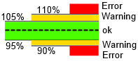 Fig.126: Representation of warning thresholds
The percentage value (e.g. here: warning: 5 for ±5%, error: 10 for ±10%) must be entered in the CoE index 0x8000:11-14.
- If the EtherCAT connection fails, the EL2595 can automatically go into an auto-flash mode. The failure is detected by the SM watchdog (default setting 100 ms).
i. 0x8002:04 = TRUE, Enable emergency flash
II. 0x8003:ff the flash sequence is set here as on/off times [ms]
0 = deactivated; an on/off pair must always be used - Limitation of the pulse time for all operation modes to protect the connected HW, can also be used for cooling the LED
i. Set in 0x8000:09 and 0x8000:0A
II. 0 = deactivated, no monitoring takes place
iii. The ReadyToActivate PDO is FALSE as long as the OFF time is running - EnableAutomaticResetOnError in 0x8002:05
If an error occurred during the pulse (signaled in the PDO and DiagData), the error message is automatically deleted if the output is set to FALSE. Otherwise a manual Reset via the PDO is necessary. - EnableAutomaticSavingOfCounter in 0x8002:06
If activated, operating hour counter 0x9000:11 (unit [minute]) and switching counter 0x9000:12 are saved locally every 15 minutes. Saving also takes place on the state transition OP → INIT or on request by command - The information to be transmitted for the real-time diagnosis can be set in 0x8002:11 and 0x8002:19.
- Operation mode of the input
- i. Normal input: no particular function for the LED function, standard input
ii. HW Enable: if this function is set, the Emergency auto-flash mode is only active if TRUE is present at the input.
iii. Trigger: - 1. If the PulseOn/Off time from 0x8000:09 /0A = 0 → each rising edge at the input toggles the LED status
2. If these times are <> 0, a pulse is output as defined in the times
3. The jitter for the internal acceptance of the trigger signal is about 5 μs - Diagnosis over CoE
i. 0x9000:01, bit-by-bit collection of various data, list to follow
II. 0x9000:08, current output voltage
iii. 0x9000:09, last measured current value in the ON state
iv. 0x9000:11, totaled On operating time of the LED in [min]; all ON times are added together, even if a pulse is only a few µs long
v. 0xA000:01, saturated: Output stage is overloaded, target voltage can no longer be maintained
vi. 0xA000:04,05, 0A, 0B: Warning based on the thresholds from 0x8000:11-14; if 0xA000:09 is set at the same time, it is the corresponding error message
vii. 0xA000:06, current > 4.2 A for several cycles is evaluated as an external short-circuit
viii. 0xF900, supply current: Maximum value since last reading; it is deleted after reading
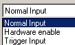 Fig.127: Selection of the mode of operation
6. For safety’s sake these CoE data can also be entered into the Startup list. If the EL2595 is exchanged later, the online CoE data are no longer available. The system manager then writes the data to the new terminal.
7. The output can now be switched on via the process data (PDO) Control.Output = TRUE or a pulse of a defined length can be output in DC mode via a timestamp.
8. The present set output current can also be specified from the controller by cyclic PDO:
- Activate PDO
- To switch on the terminal, specify a current value [mA] and then switch on the output by Control.Output = TRUE.
- The CoE values 0x8000:02, 0x8000:04 are then the upper limiters for the operation. Nevertheless, a forward voltage suitable for the load must be specified in the CoE (see above) for a correct forward current.
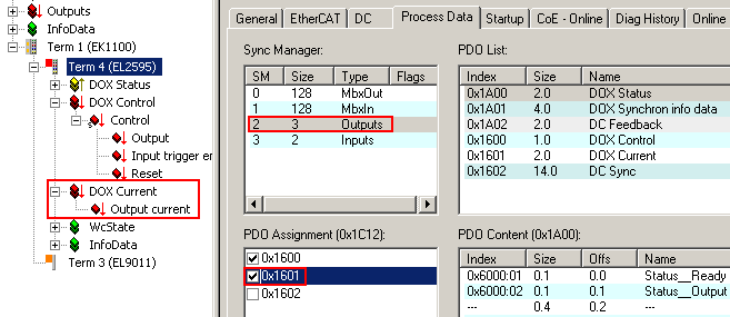 Fig.128: Activating PDO
Additional Notes
- 2013-04-19: Serial/parallel switching of several EL2595s in parallel via the SyncIn/Out connection is not yet implemented.
- The output voltage Uout may not lie within a window of Uin ±10%.