Quick start
Connecting the terminal
Install the terminal as described in the chapter entitled Installation.
Parameterizing the terminal
The terminal is factory-set such that in most applications it is operational without further parameterization.
Set the parameter "Max Current [%]" (0x8pp0:10) such that the maximum inductance current is not exceeded. If an EL2535-0000 with 1 A rated current and an inductance with a maximum current of 500 mA is used, this parameter can be set to 50 (50%). This means that, at a maximum process data value of 32767dec a coil current of +500 mA is reached (not +1 A).
Info data objects
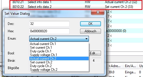
Via the info data objects additional information can be transferred synchronously. For each channel two of these objects are available. The synchronous info data can be activated in the TwinCAT System Manager, "Process data" tab (0x1A01 and 0x1A03). Objects 0x8pp0:21 and 0x8pp0:22 can be used to set the value to be transferred synchronously.
The following entries are available:
|
Value |
Text |
Description |
|---|---|---|
|
0 + Channeloffset* |
Actual current |
Actual current.. A value of 1024 corresponds to the rated terminal current |
|
1 + Channeloffset* |
Set current |
Set current. A value of 1024 corresponds to the rated terminal current |
|
2 + Channeloffset* |
Duty Cycle |
The PWM duty cycle of the output stage. A value of 1000 corresponds to 100% duty cycle. |
|
3 + Channeloffset* |
Supply voltage |
Supply voltage of the PWM output stage in mV |
*channel offset = channel number * 0x20 (channel 1 = 0x00; channel 2 = 0x20 etc.)
Watchdog
The analog output value can, e.g. in the case of a failure of communication with the controller, be set to a user-specific value. Three parameterization options are available for this purpose:
|
Watchdog object (0x8pp0:05) |
Behavior |
|---|---|
|
0: Default watchdog value |
The default value (0x8pp0:0D) is activated in the event of an error. |
|
1: Watchdog ramp active |
On error the output value is moved to the default value (0x8pp0:0D) with the ramp time set under 0x8pp0:0E |
|
2: Last output value active |
In the event of a fault (watchdog drop) the last process data is issued. |
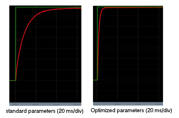
Optimization of the current control parameters
In order to support as many loads as possible ex works, the terminal has been parameterized with a moderate control behavior. Current regulation can be improved significantly by adapting the controller parameters to the actual load. To determine the settings a current pulse is applied to the load. This pulse can be picked up with an oscilloscope or with TwinCAT ScopeView.
For analysis with TwinCAT ScopeView the set and actual current is displayed in the synchronous info data.
The required step response can be set using the parameters Kp,Ki, and Kd (0x8pp0:12 to 0x8pp0:14).
Dithering
Dithering involves modulating a rectangular signal on top of the actual output value. The applied signal results in continuous movement of a valve piston, for example.
This reduces static friction and prevents sudden "breakaway" of the piston.
The configuration required for this depends a lot on the particular application.
To activate dither set object 0x8pp0:03 ("Enable dithering") and control bit CB1.0.
The following parameters can be set:
|
Value |
Text |
Description |
|---|---|---|
|
Dithering frequency [Hz] |
Frequency of the applied dither in Hz | |
|
Dithering amplitude [%] |
Amplitude of the applied dither (in % of the rated terminal current) |
The controller parameters themselves (Kp,Ki, and Kd) also play a role.
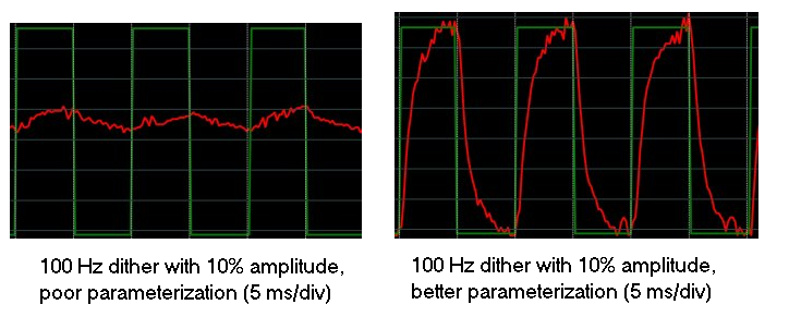
In the diagrams a dither of 10% of the rated current is shown as 100 Hz.
The controller has 5 ms for compensating a current pulse of 10%. The steepness of the current rise is limited by the controller parameters and the inductance.
The actual current should follow the set current. This is enabled through suitable settings of the controller and dither parameters (frequency and amplitude).