LED indicators
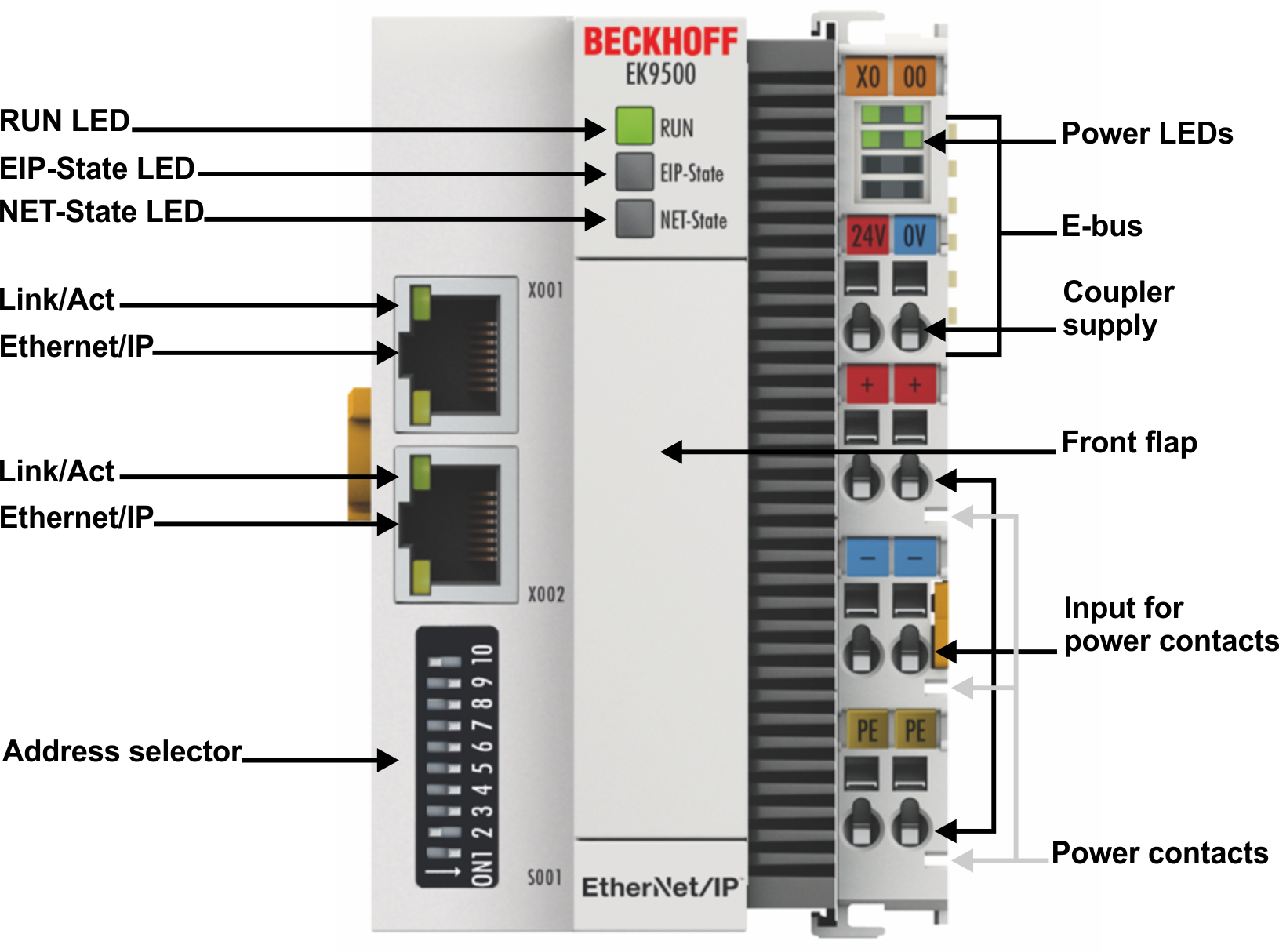
Ethernet interface
Interface X001/X002 | Ethernet | Meaning |
|---|---|---|
LED green | On/flickering (blinking) | Link available/activity |
LED yellow | is not used | - |
LED on the coupler
Labelling | Meaning | Color | Meaning |
|---|---|---|---|
RUN | Indicates the status of the coupler | red | May only light up during the start-up phase |
Green | Coupler is ready | ||
Blue | The internal Flash can be reached via USB (firmware update) |
LED EIP State
Color green | Color red | Meaning |
|---|---|---|
on | off | The coupler is in data exchange with EhterNet/IP-Scanner (Master), cyclic exchange of valid process data. |
off (1 s) | off | EtherNet/IP slave and IO assembly are correctly parameterized |
flashes (400 ms) | off | The EtherNet/IP slave has no valid IO assembly configuration |
off | off (1 s) | A general error occurred with the EtherNet/IP slave |
off | on | Internal error. Replace the coupler |
LED NET State
Color green | Color red | Meaning |
|---|---|---|
off | off | No link detected |
on | off | Coupler has detected a link and was configured correctly |
flashes (400 ms) | off | The Ethernet port has an active link and the EtherNet/IP Slave interface has no valid IP address. |
off (1 s) | off | The EtherNet/I slave has a valid IP address. UDP and TCP Layer was initialized |
off | on | Internal error. Replace the coupler |
off | off (1 s) | A general error occurred with the EtherNet/IP slave |
LEDs starting up
Run | EIP State | NET State | Meaning |
|---|---|---|---|
off | off | off | No electrical voltage connected to E-bus. Coupler must be exchanged if EtherCAT Terminals behind it need to function. |
off | off | red | LED is on and flashes a few times, after 3sec switch to off BOOT load CPU |
off | off | off | 3..4 sec Firmware load |
red | off | off | 8 sec Firmware start |
Red/green | Yellow | - | Flashing fast: EtherCAT Scanning; |
Red/green | Yellow | - | Flashing slow: EtherCAT COE reading; |
Green | - | - | Start up is finished |
LEDs on power supply terminal
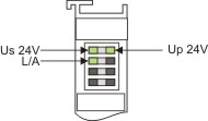
Operation with E-bus terminals
Display LED | Description | Meaning |
|---|---|---|
1 Us 24 V (top left, 1st row) | Supply voltage | on: connected to: 24 V |
2 Up 24 V (top right, 1st row) | Power contacts supply voltage | on: connected to: 24 V |
3 L/A (left center, 2nd row) | EtherCAT LED | flashing green: EtherCAT communication active |