Diagnostic LEDs
Ethernet interface X001
|
Interface X001/X002 |
Ethernet (CX8090) |
Meaning |
|---|---|---|
|
LED green |
on |
Link available/activity |
|
LED yellow |
is not used |
- |
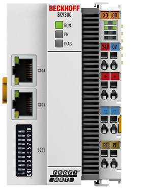
LEDs coupler
Labelling | Meaning | Color | Meaning |
|---|---|---|---|
RUN | Indicates the status of the coupler | red | May only light up during the start-up phase |
Green | Coupler is ready | ||
Blue | The internal Flash can be reached via USB (firmware update) |
LED PN | PROFINET status | Meaning | |
|---|---|---|---|
green | red | ||
Power On | off | 200 ms flashing | Start-up phase |
No name | 200 ms flashing | off | no Profinet name |
No IP | 1 s off, 200 ms on | off | No IP address |
Run | on | off | OK |
LED DIAG | PROFINET diagnosis | Meaning | |
|---|---|---|---|
green | red | ||
Flashing, PN controller identification | 500 ms | 500 ms | The PN controller is transmitting an identification signal |
No AR established | off | 200 ms flashing | The establishment of a connection with the controller has not been completed |
Device is in IO exchange | 1 s off, 200 ms on | off | Problem with establishment of a connection or nominal and actual configuration differ |
Device is in IO exchange but provider is in stop | 200 ms | off | Coupler is in data exchange, but PLC is in stop |
Device is in IO exchange | on | off | OK |
LED power supply terminal
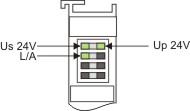
Operation with E-bus terminals
|
Display LED |
Description |
Meaning |
|---|---|---|
|
1 Us 24 V (top left, 1st row) |
CX8000 supply voltage |
on: connected to: 24 V |
|
2 Up 24 V (top right, 1st row) |
Power contacts supply voltage |
on: connected to: 24 V |
|
3 L/A (left center, 2nd row) |
EtherCAT LED |
flashing green: EtherCAT communication active |