LED indicators
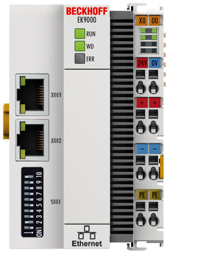
Ethernet interface X001
|
Interface X001/X002 |
Ethernet |
Meaning |
|---|---|---|
|
LED green |
on |
Link available/activity |
|
LED yellow |
is not used |
- |
LEDs on the coupler
|
Labelling |
Meaning |
Colours |
Meaning |
|---|---|---|---|
|
RUN |
Indicates the status of the coupler |
red |
May only light up during the start-up phase |
|
green |
Coupler is ready | ||
|
blue (If red DIP switch 1 is set to on when starting the coupler) |
The internal Flash can be reached via USB (firmware update) |
|
LED WD |
Modbus Status |
Meaning |
|---|---|---|
|
green/red/yellow | ||
|
EtherCAT bootup |
yellow 200 ms flashing |
EC master booting up, Modbus communication not yet possible |
|
Parameterization of the terminals |
yellow 400 ms flashing |
EC master parameterizing the EC Terminals, Modbus communication not yet possible |
|
Run |
green on |
OK |
|
Watchdog |
red 400 ms flashing |
Watchdog error |
|
LED ERR |
Modbus diagnosis |
Meaning | |
|---|---|---|---|
|
green |
red | ||
|
Modbus error |
off |
briefly lights up |
Erroneous Modbus telegram received (see Diag History) |
|
Coupler IP setting |
off |
flashing 400 ms |
Coupler has no IP address (DHCP active) |
|
Device is in IO exchange |
off |
off |
OK |
|
2nd Client |
on |
off |
2nd client is active, but write telegrams are responded to with an error |
LEDs on the power supply terminal
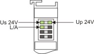
Operation with E-bus terminals
|
Display LED |
Description |
Meaning |
|---|---|---|
|
1 Us 24 V (top left, 1st row) |
Coupler supply voltage |
connected to -24 V |
|
2 Up 24 V (top right, 1st row) |
Power contacts supply voltage |
connected to -24 V |
|
3 L/A (left center, 2nd row) |
EtherCAT LED |
flashing green: EtherCAT communication active |