Notes for installation and commissioning
 | The accuracy of the TC-temperature-measurement is directly affected by the cold-junction-measurement. So some design guidelines have to be followed!
|
Notes for measurement of cold-junction-temperature
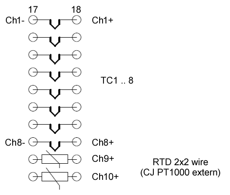
Measurement and calculation of the correct temperature with TC-elements require also to measure the so called cold-junction-temperature. The cold-junction-temperature is measured by two RTDs. They should be connected very close to the connection of TCs onto the backplane (change from TC-material to copper).
Examples:
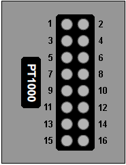
- One isothermal block → all TC-connections on the backplane are located closely at one place and have the same temperature:
- one RTD is sufficient, any TC can be referenced to e.g. “RTD1”
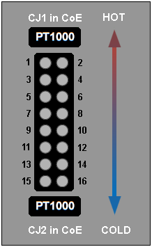
One isothermal block - Two isothermal blocks with different temperatures and each with an own RTD:
- the number of TCs on the one and the other block can be freely selected, e.g. TCs 1-3-4-7-8 close to RTD1 and TCs 2-5-6 close to RTD2.
- If there is a temperature gradient along the connecting terminals of the TCs,
- an average temperature of RTD1 and RTD2 could be calculated by a PLC and provided as process data.
- In this case the TC-channels 1 .. 4 should be referenced to CJ1, the TC-channels 5 .. 8 should be referenced to CJ2.
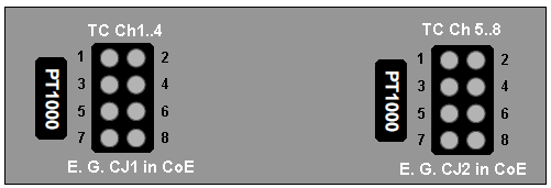
Temperature gradient along the connecting terminals of the TCs - If necessary the TC-channels can be routed to two different TC-connectors. Follow the rules mentioned above!
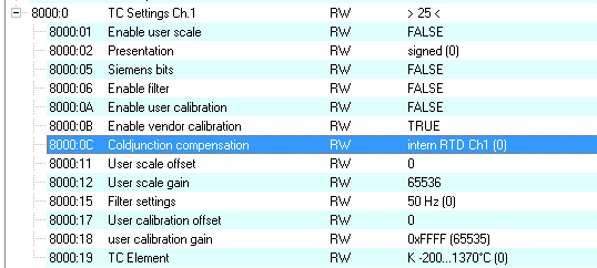
Settings of coldjuction compensation
Preset for each channel is intern RTD Ch1, the assignment can be chosen separately for each channel in index 0x80n0:0C (n=0: Channel 1 .. n=7: Channel 8).
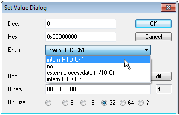
Name | Value | Description |
|---|---|---|
intern RTD Ch1 | 0dec | The coldjunction compensation takes place via intern RTD Ch1 of the module (default). |
no | 1dec | The coldjunction compensation is not active |
extern processdata (1/10°C) | 2dec | The coldjunction compensation takes place via the process data 0x160n (n=0: Channel 1 .. n=7: Channel 8). These must then be mapped via the PDO assignment. |
intern RTD Ch2 | 3dec | The coldjunction compensation takes place via intern RTD Ch2 of the module. |
Other settings:
- Filter: the index 0x8000:15 is valid for all channels, default 50 Hz
- Index 0x80x0:18 - TC element setting for each channel separately