Network interface
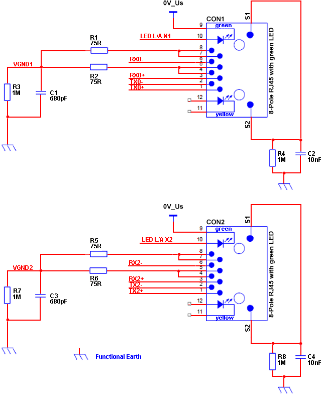 Example schematic of a RJ45 based network interface
- The RXn+, RXn- and TXn+, TXn- shall be routed as differential pairs.
- The impedance between the differential traces shall be 100 Ω.
- VGND [x1] and VGND [x2] are virtual grounds and should not be connected to other ground areas.
- VGND1 and VGND2 shall be designed as local ground areas.
- The Link Activity LEDs shall be referenced to 0V Us
- Spare- (R1-R4) - and EMI (R5-R8, C1-C4) -circuits should be adapted to EMI requirements of the application.