Activating KL6xx1 mode
The KL6xx1 mode can be used for any serial protocols. Custom protocols or other open protocols can also be used.
This mode behaves like other Beckhoff terminals with serial interface. It means that the programming and the interface is similar to a serial interface. The Beckhoff supplement blocks (such as ModbusRTU, COMLIB, ...) of the serial interface usually offer the 64-byte mode for the PC interface.
Requirements:
- The CX8180 Embedded-PC was selected as the target system.
Proceed as follows:
- 1. Click Device 2 (RS232) or Device 3 (RS485) in the tree view on the left.
- 2. Click the Communication Properties tab.
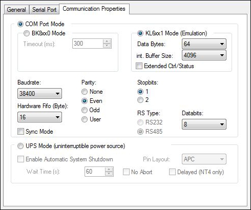
- 3. Click the option KL6xx1 Mode (Emulation) to use the CX8180 for all other protocols.
- You have successfully activated the KL6xx1 mode. Follow the same steps to deactivate the KL6xx1 mode.
Programming
Alternatively, you can operate and program the interface yourself. The data structure consists of a control and status word (2 bytes) and a data array. The control byte is written by the PLC program and acknowledges the sending of data with the TR bit.
The data (bits 4 to 15) are transmitted when an edge change (toggle) is encountered. The RA bit acknowledges that the receive data have been read. This enables the interface to recognize that it can copy new data into the data array. The status word indicates how many data are valid. When a positive edge is encountered, the IR bit (Reset) clears the buffers and resets the interface. The interface acknowledges the command in the status word with the IA bit. Finally, the IR bit is set to "False" again.
Bit | 15 | 14 | 13 | 12 | 11 | 10 | 09 | 08 | 07 | 06 | 05 | 04 | 03 | 02 | 01 | 00 |
Name | Length of data to be written (OL bits) | reserve | IR bit | RA bit | TR bit | |||||||||||
Bit | Name | Comment | |
|---|---|---|---|
CW.3 | Reserved | - | - |
CW.2 | IR | 1bin | The controller requests initialization. The send and receive functions are blocked, the FIFO indicators are reset, and the interface is again initialized with the value. The interface acknowledges completion of the initialization via bit SW.2 (IA). |
0bin | The controller once again requests the interface to prepare for serial data exchange. | ||
CW.1 | RA | toggle | The controller acknowledges receipt of data by changing the state of this bit. Only then new data can be transferred from the interface to the controller. |
CW.0 | TR | toggle | Via a change of state of this bit the controller notifies the interface that the DataOut bytes contain the number of bytes indicated via the OL bits. The interface acknowledges receipt of the data in the status word via a change of state of bit SW.0 (TA). Only now new data can be transferred from the controller to the interface. |
Bit | 15 | 14 | 13 | 12 | 11 | 10 | 09 | 08 | 07 | 06 | 05 | 04 | 03 | 02 | 01 | 00 |
Name | Length of data in the buffer ((IL bits) | BUF_F | IA bit | RR bit | TA bit | |||||||||||
Bit | Name | Comment | |
|---|---|---|---|
SW.3 | BUF_F (buffer full) | 1bin | The receive FIFO is full. All further incoming data will be lost! |
SW.2 | IA | 1bin | Initialization was completed by the interface. |
0bin | The interface is ready again for serial data exchange. | ||
SW.1 | RR | toggle | Via a change of state of this bit the interface notifies the controller that the DataIn bytes contain the number of bytes indicated via the IL bits. The controller has to acknowledge receipt of the data in the control word via a change of state of bit CW.1 (RA). Only then new data can be transferred from the interface to the controller. |
SW.0 | TA | toggle | The interface acknowledges receipt of data by changing the state of this bit. Only now new data can be transferred from the controller to the interface. |
Example
In this sample program, the operating principle is explained using the RS232 interface. Data is sent via the RS232 interface and received via a bridge (PIN 2 to 3).
Download: cx8080_rs232.zip