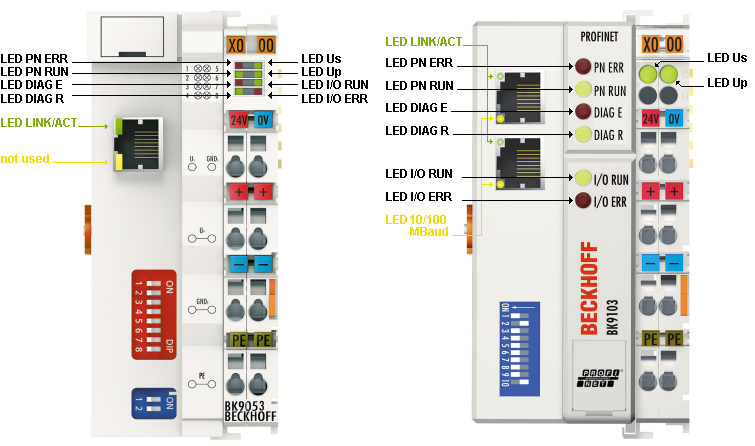
Diagnostic LEDs
After switching on, the Bus Coupler immediately checks the connected configuration. Error-free start-up is indicated when the red I/O ERR LED goes out. If the I/O ERR LED blinks, an error in the area of the terminals is indicated. The error code can be determined from the frequency and number of blinks. This permits rapid rectification of the error.
The Bus Coupler has two groups of LEDs for the display of status. The upper group with four LEDs indicates the status of the respective fieldbus. The significance of the fieldbus status LEDs is explained in the appropriate sections of this manual. It corresponds to the usual fieldbus display.
On the upper right hand side of the Bus Couplers are two more green LEDs that indicate the supply voltage. The left hand LED indicates the presence of the 24 V supply for the Bus Coupler. The right hand LED indicates the presence of the supply to the power contacts.
LEDs for power supply diagnostics
|
LED |
Meaning | |
|---|---|---|
|
LED Us |
off |
the power supply voltage, Us, is not present |
|
on |
the power supply voltage, Us, is present | |
|
LED Up |
off |
Supply voltage Up (for power contacts) not available |
|
on |
Supply voltage Up (for power contacts) available | |
LEDs at RJ45
|
LED |
Meaning | |
|---|---|---|
|
LED Link/Act |
off |
No physical connection present |
|
on |
Physical connection present | |
|
flashing |
Communication available | |
|
LED 10/100 Mbaud |
off |
10 Mbaud (if LED Link/Act is lit or flashes) |
|
on |
100 Mbaud | |
LEDs for PROFINET diagnostics
PROFINET diagnosis | PN Err (red) | PN Run (green) | DIAG E (red) | DIAG R (green) |
|---|---|---|---|---|
IP Address OK | off | 0,5 s | x | x |
No IP valid Address (Dip Switch 9,10 -> on) | 0,1 sec | off | x | x |
Online | off | on | x | x |
Offline PLC Stop | off | 0,1 s | x | x |
TimeOut | 0,5 s | off | x | x |
IP address configuration fault | on | off | x | x |
Alternate flashing (triggered by a Profinet tool) | 0.5 sec | 0.5 sec | x | x |
Configuration Diagnose | PN Err (red) | PN Run (green) | DIAG E (red) | DIAG R (green) |
|---|---|---|---|---|
OK | x | x | off | on |
Wrong module | x | x | Slot number | 1 |
Missing module (physical) | x | x | Slot number | 2 |
Missing module (in the configuration) | x | x | Slot number | 3 |
No PROFINET name assigned | x | x | 0 | 4 |
Substitute | x | x | Slot number | 5 |
x: The status of the LED is not relevant for this diagnosis.
Note:
- In the event of several errors the last faulty module is displayed.
- Substitute is set for incorrectly configured modules that are nevertheless executable (example: KL2xx2 was configured but KL2xx4 was inserted in the slot)
Sample
You have configured a KL2xx4 for the fifth slot, but in fact only four modules are inserted.
- Start Error Code: Red DIAG E LED flickers rapidly, green DIAG R LED is off
- Red DIAG E LED is on, green LED shows the error code and flashes twice (0.5 sec)
- Red and green LED off
- Red DIAG E LED shows the error argument and flashes 5 times (0.5 sec, in this case the slot number), green LED is off
LEDs for K-bus diagnostics
|
Error code |
Error code argument |
Description |
Remedy |
|---|---|---|---|
|
Persistent, continuous flashing |
|
EMC problems |
|
|
1 pulse |
0 |
EEPROM checksum error |
Set manufacturer's settings with the KS2000 configuration software |
|
1 |
Code buffer overflow |
Insert fewer Bus Terminals. Too many entries in the table for the programmed configuration | |
|
2 |
Unknown data type |
Software update required for the Bus Coupler | |
|
2 pulses |
0 |
Programmed configuration has an incorrect table entry |
Check programmed configuration for correctness |
|
n (n > 0) |
Table comparison (Bus Terminal n) |
Incorrect table entry | |
|
3 pulses |
0 |
K-bus command error |
|
|
4 pulses |
0 |
K-bus data error, break behind the Bus Coupler |
Check whether the n+1 Bus Terminal is correctly connected; replace if necessary. |
|
n |
Break behind Bus Terminal n |
Check whether the bus end terminal 9010 is connected. | |
|
5 pulses |
n |
K-bus error in register communication with Bus Terminal n |
Exchange the nth bus terminal |
|
6 pulses |
0 |
Error at initialization |
Exchange Bus Coupler |
|
1 |
Internal data error |
Perform a hardware reset on the Bus Coupler (switch off and on again) | |
|
4 |
DIP switch incorrect for BootP |
Set 1-8 to on or off, see BootP | |
|
8 |
Internal data error |
Perform a hardware reset on the Bus Coupler (switch off and on again) | |
|
16 |
Error in IP socket |
Perform a hardware reset on the Bus Coupler (switch off and on again) | |
|
14 pulses |
n |
nth Bus Terminal has the wrong format |
Start the Bus Coupler again, and if the error occurs again then exchange the Bus Terminal |
|
15 pulses |
n |
Number of Bus Terminals is no longer correct |
Start the Bus Coupler again. If the error occurs again, restore the manufacturers setting using the KS2000 configuration software |
|
16 pulses |
n |
Length of the K-bus data is no longer correct |
Start the Bus Coupler again. If the error occurs again, restore the manufacturers setting using the KS2000 configuration software |