BK9103 - introduction
The BK9103 Bus Coupler connects PROFINET with the modular, extendable electronic terminal blocks. A unit consists of a Bus Coupler, any number (between 1 and 64) of terminals, and a bus end terminal (255 Bus Terminals with Terminal Bus extension).
The Bus Couplers recognize the terminals to which they are connected, and perform the assignment of the inputs and outputs to the words of the process image automatically.
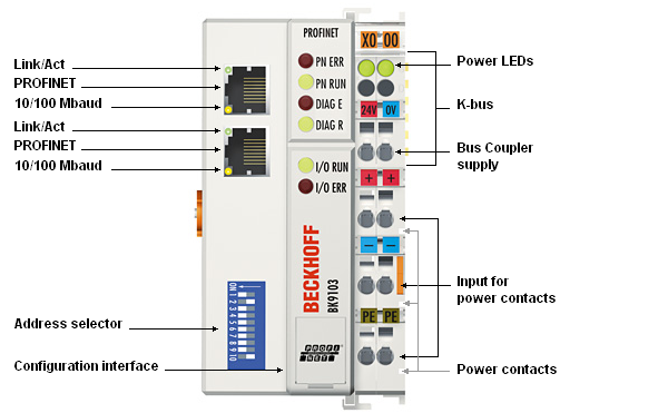
The BK9103 Bus Coupler supports 10 Mbit/s and 100 Mbit/s Ethernet. Connection is through normal RJ 45 connectors. The IP address is set on a DIP switch (the offset from a freely selectable start address). In networks with DHCP (a service for the allocation of the logical IP address to the physical node address (MAC-ID)) the Bus Coupler obtains its IP address from the DHCP server.
The BK9103 has an additional RJ-45 port. Both Ethernet ports operate as 2-channel switches. The I/O stations can thus be configured with a line topology, instead of the classic star topology. In many applications; this significantly reduces the wiring effort and the cabling costs. The maximum distance between two couplers is 100 m. Up to 20 BK9103 Bus Couplers are cascadable, so that a maximum line length of 2 km can be achieved.
Complex signal processing for analog I/Os, displacement measurement, etc.
The BK9000 Bus Coupler supports operation of all K-Bus Terminals. As far as the user is concerned, the inputs and outputs are not handled any differently from the way they are by other coupler series. The information is made available for use as a byte array in the process image of the automation device.
The KS2000 configuration software allows the analog and multifunctional Bus Terminals to be adapted to the specific application. Depending on the particular type, the registers in the analog Bus Terminals contain temperature ranges, amplification factors and linearization curves. The KS2000 software can be used to set the desired paramétrisation via the PC. The Bus Terminal stores the setting permanently, even if the voltage supply fails. Having the controller (PLC, IPC) carry out the configuration of the Bus Terminals is a further option. The PLC or IPC uses function blocks (FB) to take care of the configuration of all the peripherals during the start-up phase. The controller can, if required, upload the non-centrally generated configuration data in order to manage and store them centrally. This means that it is not necessary to carry out the setting procedure again if a Bus Terminal is exchanged. The controller carries out the desired setting automatically after switching on.