LEDs
After switching on, the Bus Coupler immediately checks the connected configuration. Error-free start-up is signaled by the red LED I/O ERR being extinguished. If the I/O ERR LED blinks, an error in the area of the terminals is indicated. The frequency and number of flashes indicate the error code (see below).
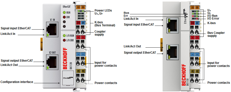
The BK1120 / BK1150 Bus Coupler has a green LED Link/Act In / Link/Act Out at the RJ45 sockets, which indicates the fieldbus status.
The RUN and ERROR LEDs (for BK1120: center top, for BK1150: left row of the LED prism) indicate the state of the EtherCAT state machine.
On the upper right hand side of the BK1120 are two more green LEDs that indicate the supply voltage. The left hand LED indicates the presence of the 24 V supply for the Bus Coupler. The right hand LED indicates the presence of the supply to the power contacts. At the BK1150, the diagnostic LEDs are on the right side of the LED prism, as shown in Fig. BK1120, BK1150 - Diagnostic LEDs at Bus Coupler.
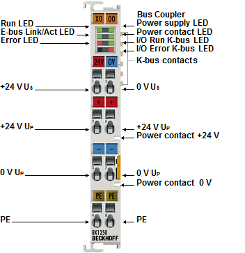
The diagnostic LEDs for the BK1250 are arranged as shown in Fig. BK1250 - Diagnostic LEDs at Bus Coupler.
LEDs for power supply diagnostics
LED | Display | State | Description | |
|---|---|---|---|---|
Us (POWER SUPPLY) | green | off | - | No operating voltage present at the Bus Coupler |
on | - | 24 VDC operating voltage present at the Bus Coupler | ||
Up (POWER CONTACTS) | green | off | - | No power supply present at the power contacts |
on | - | 24 VDC power supply present at the power contacts | ||
Diagnostic LEDs for the EtherCAT State Machine/PLC
LED | Display | State | Description | |
|---|---|---|---|---|
RUN | green | off | Init | The Bus Coupler is in initialization state |
flashing | Pre-Operational | The Bus Coupler is in pre-operational state | ||
single flash | Safe-Operational | The Bus Coupler is in safe-operational state | ||
on | Operational | The Bus Coupler is in operational state | ||
flickers | Bootstrap | Firmware is being loaded. | ||
ERROR | red | off | - | No error |
flashing | Err-Operational | PLC error / lost frames | ||
LEDs for fieldbus diagnostics
BK1120, BK1150 | ||||
|---|---|---|---|---|
LED | Display | State | Description | |
LINK / ACT (X1 IN) | green | off | - | No connection on the incoming EtherCAT segment |
on | linked | Preceding EtherCAT device connected | ||
flashing | active | Communication with preceding EtherCAT device | ||
LINK / ACT (X2 OUT) | green | off | - | No connection on the outgoing EtherCAT segment |
on | linked | Following EtherCAT device connected | ||
flashing | active | Communication with downstream EtherCAT device | ||
BK1250 | ||||
|---|---|---|---|---|
LED | Display | State | Description | |
LINK/ACT | green | off | - | No connection/communication with the E-bus |
flashing | linked | Connection/communication with the E-bus established | ||
LEDs for K-bus diagnostics
LED | Display | State | Description | ||
|---|---|---|---|---|---|
I/O-RUN | green | off | - | K-bus inactive | |
on | - | K-bus active | |||
LED red; I/O-Error | Error code argument | Description | Remedy | ||
Persistent, continuous flashing |
| EMC problems |
| ||
1 pulse | 0 | EEPROM checksum error |
| ||
1 | Code buffer overflow |
| |||
2 | Unknown data type |
| |||
2 pulses | 0 | Programmed configuration has an incorrect table entry |
| ||
n (n > 0) | Table comparison (Bus Terminal n) |
| |||
3 pulses | 0 | K-bus command error |
| ||
4 pulses | 0 | K-bus data error, break behind the Bus Coupler |
| ||
n | Break behind Bus Terminal n |
| |||
5 pulses | n | K-bus error in register communication with Bus Terminal n |
| ||
14 pulses | n | nth Bus Terminal has the wrong format |
| ||
15 pulses | n | Number of Bus Terminals is no longer correct |
| ||
16 pulses | n | Length of the K-bus data is no longer correct |
| ||