Image showing AX5118, AX5125 and AX5140
The servo drive illustrated below is an AX5140; the devices with 18 A or 25 A are structurally similar apart from pos. 11 "X07" (external brake resistor).
|
|
|
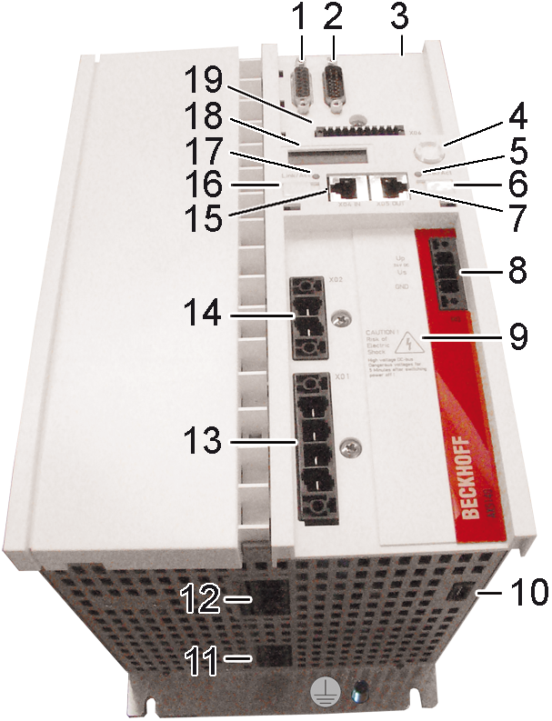
Pos. | Name | Pos. | Name | |
|---|---|---|---|---|
1 | X11 - feedback connection, encoder | 11 | X07 - external brake resistor (only AX5140) | |
2 | X12 - feedback connection, resolver | 12 | X13 - motor connection (U, V, W, PE) | |
3 | X3x - optional slot for safety card | 13 | X01 - mains supply 100 - 480 V | |
4 | Navigation rocker | 14 | X02 – DC link output (max. voltage 875 V DC), connection for external brake resistor | |
5 | Status LED for EtherCAT output | 15 | X04 - socket for EtherCAT input | |
6 | Labelling field | 16 | Labelling field | |
7 | X05 - socket for EtherCAT output | 17 | Status LED for EtherCAT input | |
8 | X03 - power supply 24 V DC input | 18 | Display | |
9 |
DANGER | Max. voltage 875 V DC at the DC link terminals (X02). Dangerous voltage continues to be present for around 5 minutes after the device has been switched off (AX5140 = 15 min.). The device is safe once the voltage has fallen below 50 V. | 19 | X06 - connection for digital inputs and outputs |
10 | X14 – sensor for motor temperature, brake and OCT |
|
| |