Layout of the wiring
Using the offset calculated in the previous section, the wiring of the coupled motors can be done on the basis of the following table. For each case the table shows how the phases of motor 1 (L1, L2, L3) are connected to the phases of motor 2 (L1’, L2’, L3’).
|
|
Cables of the motors point in the same direction |
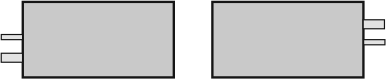
Cables of the motors point outwards |
Cables of the motors point inwards |
|---|---|---|---|
|
|
|
|
|
|
Offset = 0 |
L1/L1‘ L2/L2‘ L3/L3‘ |
L1/L1‘ L2/L3‘ L3/L2‘ |
L1/L1‘ L2/L3‘ L3/L2‘ |
|
Offset = 1 |
L1/L3‘ L2/L1‘ L3/L2‘ |
L1/L2‘ L2/L1‘ L3/L3‘ |
L1/L3‘ L2/L2‘ L3/L1‘ |
|
Offset = 2 |
L1/L2‘ L2/L3‘ L3/L1‘ |
L1/L3‘ L2/L2‘ L3/L1‘ |
L1/L2‘ L2/L1‘ L3/L3‘ |